Wellbore cleaning tool system and method of use

a wellbore and tool system technology, applied in the direction of wellbore/well accessories, fluid removal, earthwork drilling and mining, etc., can solve the problems of increasing the cost of operations, reducing the efficiency of scrapping and brushing, and accumulation of round trip delays to journal the cleaning devi

Inactive Publication Date: 2007-11-15
WELLBORE SPECIALTIES
View PDF13 Cites 65 Cited by
  • Summary
  • Abstract
  • Description
  • Claims
  • Application Information

AI Technical Summary

Benefits of technology

[0016] The preferred embodiment of wellbore cleaning tool apparatus of the present invention solves the aforementioned problems in a straight forward and simple manner.

Problems solved by technology

The mud cake may coat the blades and steel bristles and build-up thereon such that the efficiency of the scrapping and brushing is diminished.
Another of the disadvantages of known wellbore cleaning devices is the accumulation of round trip delays to journal the cleaning device down hole and to remove the cleaning device, such as each time the device needs cleaning, replacing broken parts, or before, during and after drilling operations.
The roundtrip delay time extends the time to complete drilling operations which increases the cost of operations.
Furthermore, known wellbore cleaning devices require repeated cleaning of the brushes and scraper, thus adding additional round trip delays.

Method used


Image

  • Wellbore cleaning tool system and method of use
  • Wellbore cleaning tool system and method of use
  • Wellbore cleaning tool system and method of use

Examples


Embodiment Construction

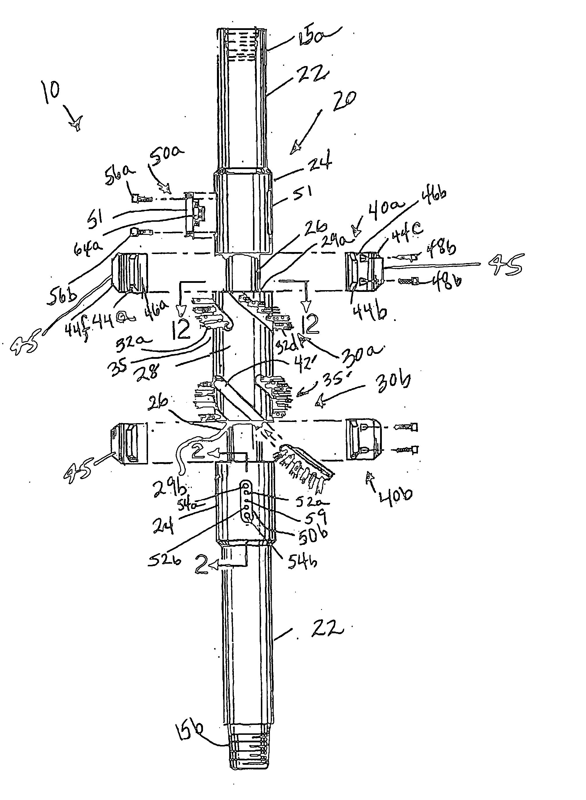
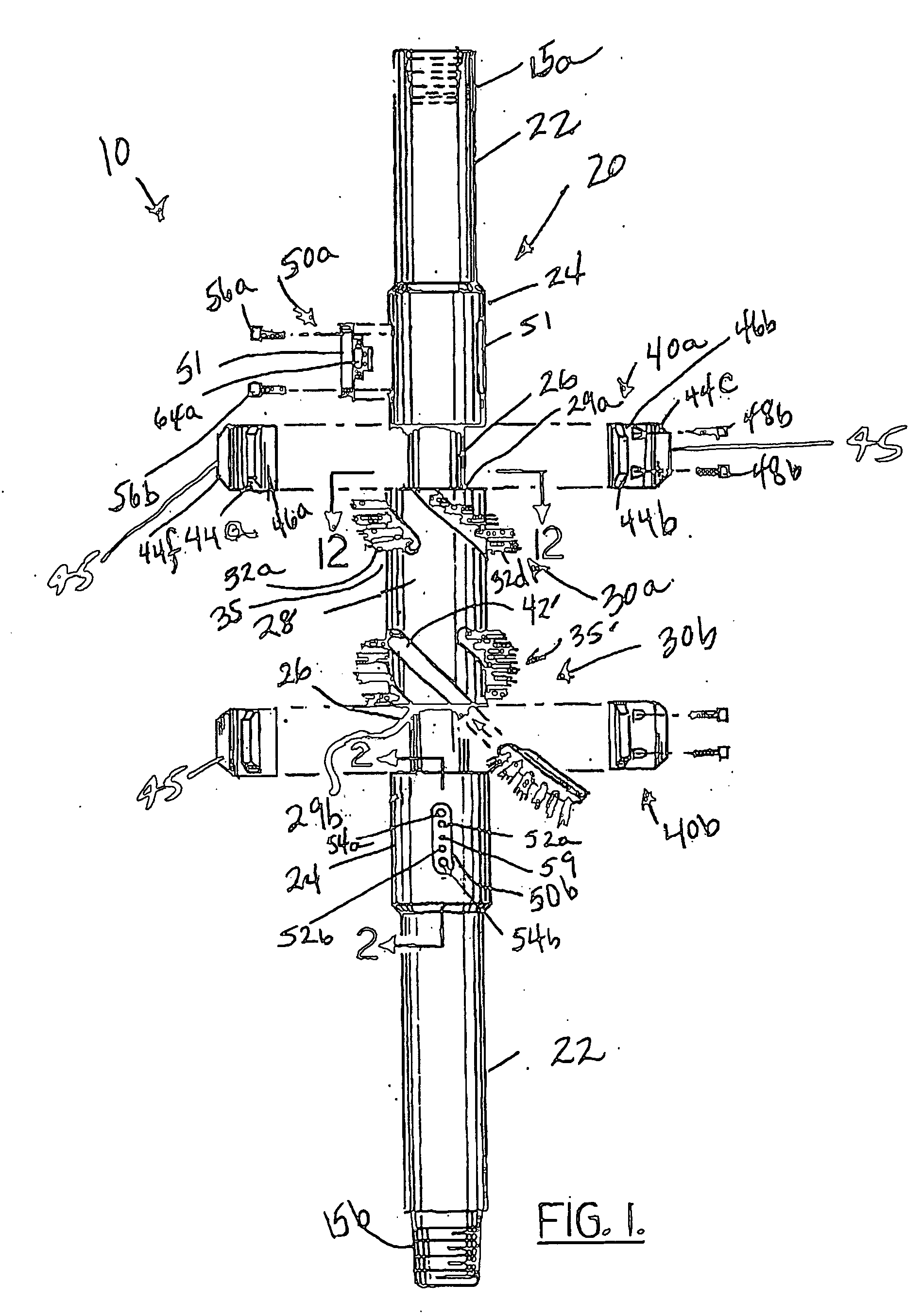
[0069] Referring now to the drawings and in particular FIGS. 1 and 14, the wellbore cleaning tool apparatus of the present invention will generally be referenced by the numeral 10 with the wellbore cleaning tool system being referenced by the numeral 100. The wellbore cleaning tool apparatus 10 includes, in general, a casing body 20 adapted to be centralized in the wellbore 5 (FIG. 24) via top and bottom stabilizers (NOT SHOWN), a plurality of sets of brushes 30a and 30b, a plurality of sets of scrapers 40a and 40b and a plurality of sets of jet spray assemblies 50a and 50b for high-velocity jet spraying of the interior wall of the wellbore 5 for an added cleanout effect. As will be seen from the description provided below, the high-velocity jet sprays also aid in cleaning the plurality of sets of brushes 30a and 30b and the plurality of sets of scrapers 40a and 40b during cleaning operations so that any build-up of the mud cake, cement sheath, etc., when being brushed or scraped fr...


PUM


Abstract

A wellbore cleaning tool system includes a plurality of brushes and scrappers supported by or mounted to a casing body to clean an interior wall of a wellbore. The cleaning tool system includes selectively actuated high-velocity jet sprays to aid the cleaning of the interior wall of a wellbore by enhance the loosening and releasing of mud cake, oily residue, cement sheath, and pipe scale. The jet sprays also aid in the cleaning operation performed by and efficiency of the brushes and scrappers by spraying, loosening and releasing matter (mud cake, oily residue, cement sheath, and pipe scale) adhering to or sticking on the brushes and scrapers.

Description

BACKGROUND OF THE INVENTION [0001] 1. Field of the Invention [0002] The present invention relates to tools for cleaning a wellbore and, more particularly, to a cleaning tool system that brushes, scrapes and selectively sprays, with high-velocity jet sprays, matter from the interior wall of a wellbore. [0003] 2. General Background [0004] Cleaning a wellbore with scraping and brushing has been employed in the oil field drilling and exploration industry. The cleaning out of the wellbore is essential so, for example, the flow of drilling fluid to the annulus of the wellbore remains unobstructed between tool casings and the interior wall of the wellbore. [0005] Drilling operations use drilling fluid (sometimes referred to as drilling fluid mud) that cakes onto the wellbore. The mud is very thick and may mix with any oil residue in the wellbore annulus. Pipe scale and cement sheath can also be found adhering to the wellbore casing or liner. When cleaning the unwanted mud cake from the wel...

Claims


Application Information

Patent Timeline
Patent Type & Authority Applications(United States)
IPC IPC(8): E21B37/00
CPCE21B37/04E21B37/02
Inventor BRUNET, TRAVISSHACKELFORD, STEVIE
Owner WELLBORE SPECIALTIES
Why Eureka
Try Eureka