Flexible channel for use on endoscope

a flexible channel and endoscope technology, applied in the field of flexible channels, to achieve the effect of maintaining positional stability, reducing the outside diameter of the flexible channel, and suitable flexibility in bending directions

a flexible channel and endoscope technology, applied in the field of flexible channels, to achieve the effect of maintaining positional stability, reducing the outside diameter of the flexible channel, and suitable flexibility in bending directions

US20070282304A1Inactive Publication Date: 2007-12-06FUJIFILM CORP

Image

  • Flexible channel for use on endoscope
  • Flexible channel for use on endoscope
  • Flexible channel for use on endoscope

Examples


Embodiment Construction

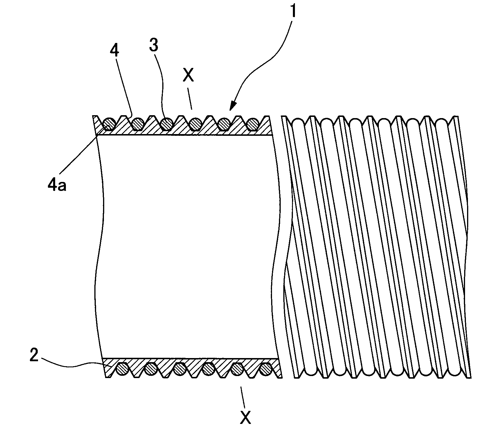
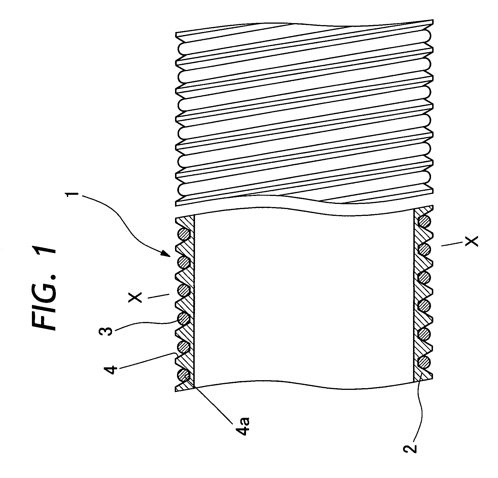
[0024]Hereafter, the present invention is described more particularly by way of its preferred embodiments. Shown in FIG. 1 is a fragmentary sectional view of a flexible channel according to the present invention. In this case, the flexible channel is extended from a manipulating head assembly to a fore distal end of an insertion portion of an endoscope to serve as the so-called biopsy channel for insertion of forceps or other medical treating instruments. However, it is to be understood that application of the flexible channel is not limited to a biopsy channel. For example, the flexible channel can be incorporated into an endoscopic insertion portion to provide a passage which is flexible in bending directions and which has satisfactory shape retainability, for example, to serve as a fluid supply passage or as a sheath of control cables.

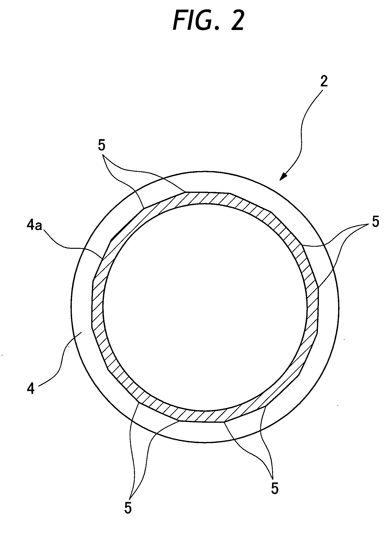
[0025]As shown in the drawing, the flexible channel 1 is composed of a flexible tube 2 and a reinforcing coil 3. The flexible tube 2 is formed of a...


PUM


Abstract

A flexible channel to be incorporated into an endoscopic insertion portion having a flexible portion at least in part of its length, for the purpose of providing a flexible passage internally of the endoscopic insertion portion. The flexible channel is composed of a flexible tube with a helical groove on and around its outer periphery, and a reinforcing coil fitted in the helical groove on the flexible tube. At the root of the helical groove, angular projections are formed at intervals in the longitudinal direction and the reinforcing coil is tightly pressed tightly against the angular projections.

Description

BACKGROUND OF THE INVENTION[0001]1. Field of the Art[0002]This invention relates to a flexible channel to be fitted in an endoscopic insertion portion to serve as a passage of forceps or other surgical or medical instruments, for insertion of operating wires or other components, or as a passage for sending a fluid into or out of a body cavity.[0003]2. Prior Art[0004]Generally, the so-called biopsy channel is provided in an endoscopic insertion portion for introduction of forceps or other treating instruments into a body cavity. The biopsy channel of this sort is extended forward from an manipulating head assembly as far as a fore distal end of an elongated insertion portion. In case the endoscopic insertion portion has a flexible section in part of its length, the biopsy channel needs to have a flexible structure in that section. Therefore, usually a biopsy channel is formed by the use of a flexible tube of a soft or pliable synthetic resin material and fitted in an endoscopic inser...

Claims


Application Information

Patent Timeline
06 Dec 2007
Publication
US20070282304A1
IPC
A61M25/00
CPC
A61B1/0011; G02B23/2476; A61B1/018; A61B1/005
Inventors
OGURA, AKIRA; WATANABE, JOJI