Ultrasonic suspension guide rail with high positioning precision

A guide rail and ultrasonic technology, which is applied to the suspension device of the wing leaf, the control mechanism of the wing leaf, door/window fittings, etc. High, low pollution effect

Active Publication Date: 2019-06-18
ZHEJIANG UNIV
View PDF8 Cites 1 Cited by
  • Summary
  • Abstract
  • Description
  • Claims
  • Application Information

AI Technical Summary

Problems solved by technology

Although this kind of guide rail has simple structure, convenient manufacture, high bearing capacity and good shock resistance, it is easy to wear and tear, and the positioning accuracy will decrease after long-term use, so it is not suitable for occasions with high precision requirements.

Method used


Image

  • Ultrasonic suspension guide rail with high positioning precision
  • Ultrasonic suspension guide rail with high positioning precision
  • Ultrasonic suspension guide rail with high positioning precision

Examples


Embodiment Construction

[0030] The present invention will be further described below in conjunction with the accompanying drawings and embodiments.

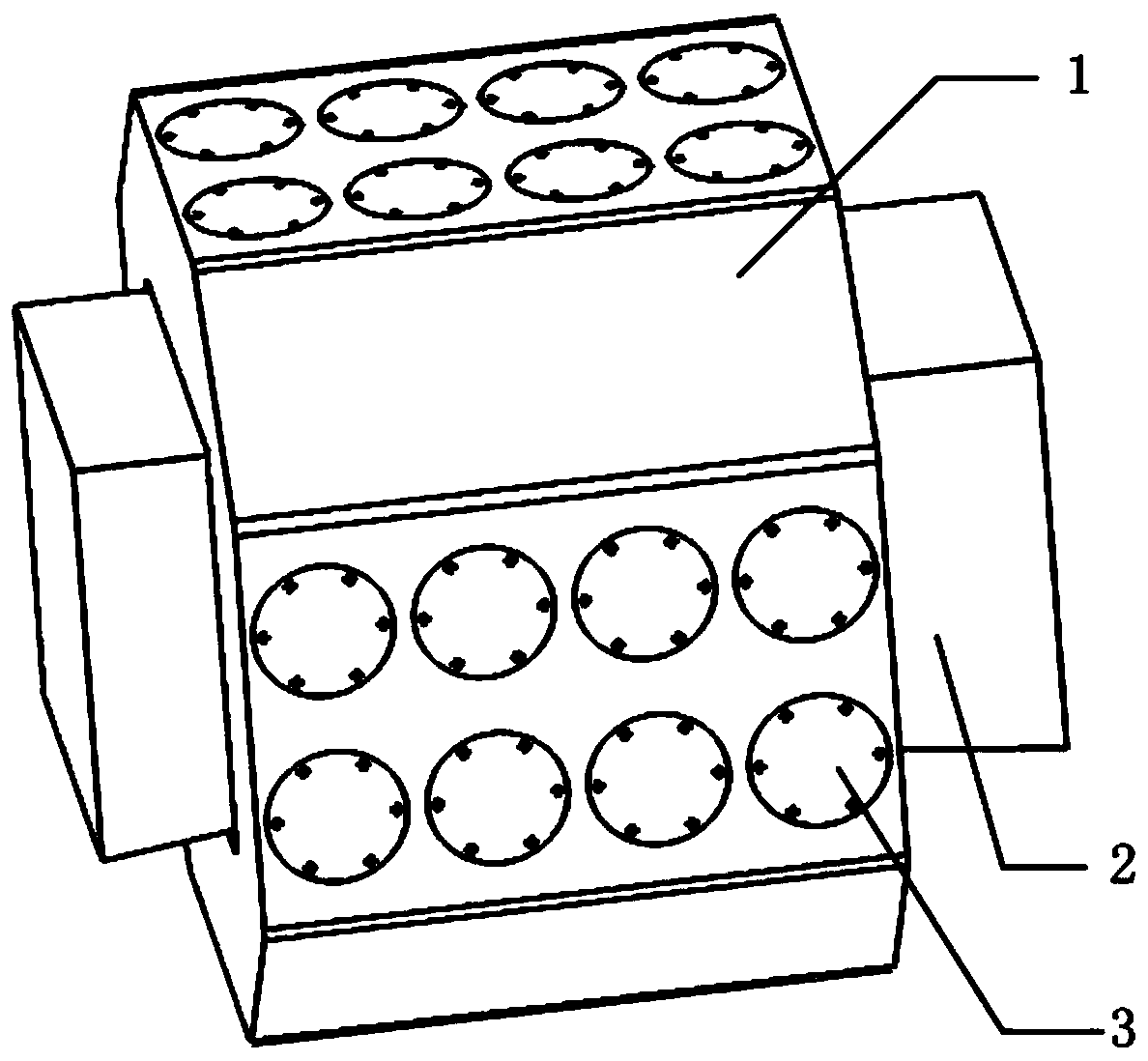
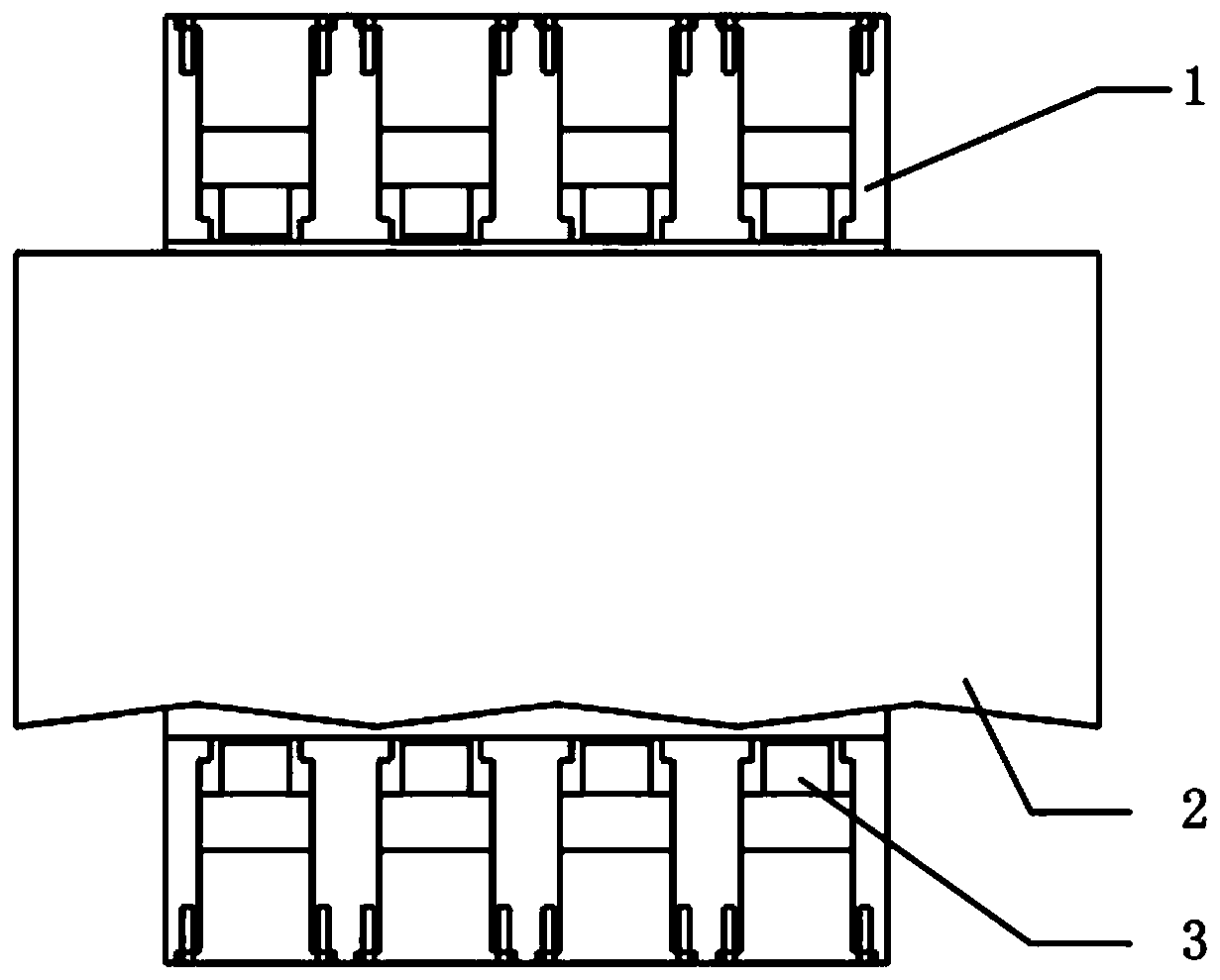
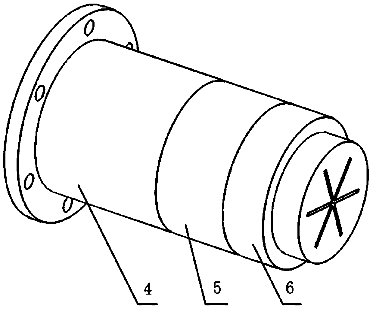
[0031] In the figure, 1. transducer bracket, 2. guide rail, 3. piezoelectric transducer, 4. rear end cover, 5. ceramic piezoelectric sheet, 6. horn.

[0032] Such as figure 1 As shown, the specific implementation of the present invention includes piezoelectric transducer 3, guide rail 2 and transducer support 1; The bracket 1 is set outside the guide rail 2, the central axis of the guide rail 3 coincides with the central axis of the piezoelectric transducer bracket, and there is a gap between the inner peripheral surface of the transducer bracket 1 and the outer circumference of the guide rail 2; the upper, lower and both sides of the transducer bracket 1 There are evenly distributed circular through-holes with the same size on the four surfaces, and the through-holes are divided into upper and lower rows, four in each row, and the distance between adj...


PUM


Abstract

The invention discloses an ultrasonic suspension guide rail with high positioning precision. A transducer bracket is of an annular structure and sleeves a guide rail body, and a gap is formed betweenthe inner circumferential face of the transducer bracket and the periphery of the guide rail body; a plurality of piezoelectric transducers arranged at different positions in the direction of the guide rail body are mounted around the upper part, the lower part and the two sides of the transducer bracket correspondingly, through holes communicating with the gap from the exterior are formed in theside wall of the transducer bracket, and the piezoelectric transducers are mounted in the through holes; and rear end covers of the piezoelectric transducers are fixed into the through holes, the tailends of amplitude-change poles are fixedly connected with the rear end covers through ceramic piezoelectric patches, snowflake-shaped grooves are formed in the end faces of the front ends of the amplitude-change poles, and the front ends of the amplitude-change poles serve as the tail ends of the piezoelectric transducers. Frictional wear is reduced, the sound intensity of ultrasonic waves is adjusted according to the distance between the bracket and the bottom of the guide rail, and thus force enabling the guide rail to move in the circumferential direction is generated.

Description

technical field [0001] The invention relates to a mechanical structure guide rail, in particular to an ultrasonic levitation guide rail with high positioning accuracy. Background technique [0002] Ordinary guide rails are in direct contact with the bracket and have a high load-carrying capacity. Although this kind of guide rail has simple structure, convenient manufacture, high bearing capacity and good shock resistance, it is easy to wear and tear, and the positioning accuracy will decrease after long-term use, so it is not suitable for occasions with high precision requirements. The near-field acoustic suspension can well reduce the contact between the bracket and the guide rail, and reduce the wear of the guide rail during operation. Contents of the invention [0003] In order to solve the problem of dimensional wear in the background technology, the purpose of the present invention is to provide an ultrasonic levitation guide rail with high positioning accuracy. Even...

Claims


Application Information

Patent Timeline
Patent Type & Authority Applications(China)
IPC IPC(8): E05D13/00E05D15/06E05F15/635E05F15/643E05F17/00
Inventor 陈通汪久根
Owner ZHEJIANG UNIV
Why Eureka
Try Eureka