Dual flapper barrier valve

a technology of flapper and barrier valve, which is applied in the direction of fluid removal, borehole/well accessories, construction, etc., can solve the problems of ball valve not working properly, no full bore access to the completion assembly,

Inactive Publication Date: 2007-12-13
WEATHERFORD TECH HLDG LLC
View PDF20 Cites 40 Cited by
  • Summary
  • Abstract
  • Description
  • Claims
  • Application Information

AI Technical Summary

Problems solved by technology

Although the ball valve is functional in isolating a portion of the completion assembly from another portion of the completion assembly, there are several drawbacks in using the ball valve in the completion assembly.
Further, the ball valve is susceptible to debris in the completion assembly which may cause the ball valve to fail to operate properly.
Additionally, if the valve member of the ball valve is not fully rotated to align the bore of the valve member with the bore of the completion assembly, then there is no full bore access of the completion assembly.

Method used


Image

  • Dual flapper barrier valve
  • Dual flapper barrier valve
  • Dual flapper barrier valve

Examples


Embodiment Construction

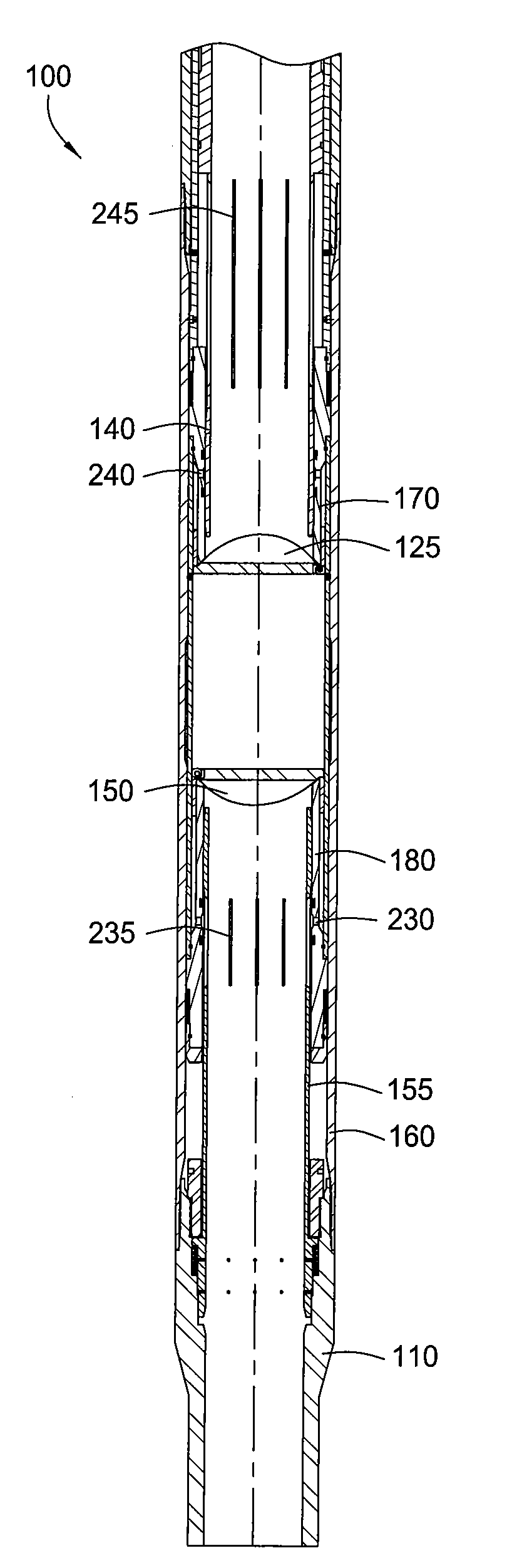
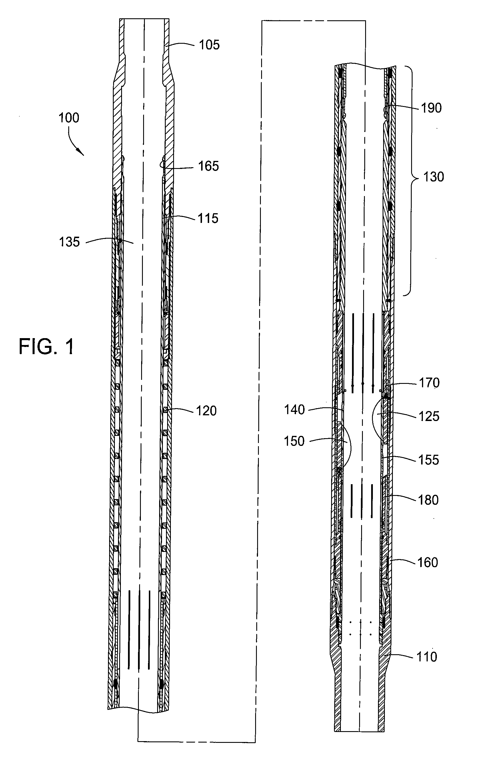
[0019]FIG. 1 is a cross-sectional view illustrating a downhole tool 100 in a run-in position. The tool 100 includes an upper sub 105, a housing 160 and a lower sub 110. The upper sub 105 is configured to be connected to an upper completion assembly (not shown), such as a packer arrangement. The lower sub 110 is configured to be connected to a lower completion assembly (not shown). Generally, the tool 100 is used to selectively isolate the upper completion assembly from the lower completion assembly.

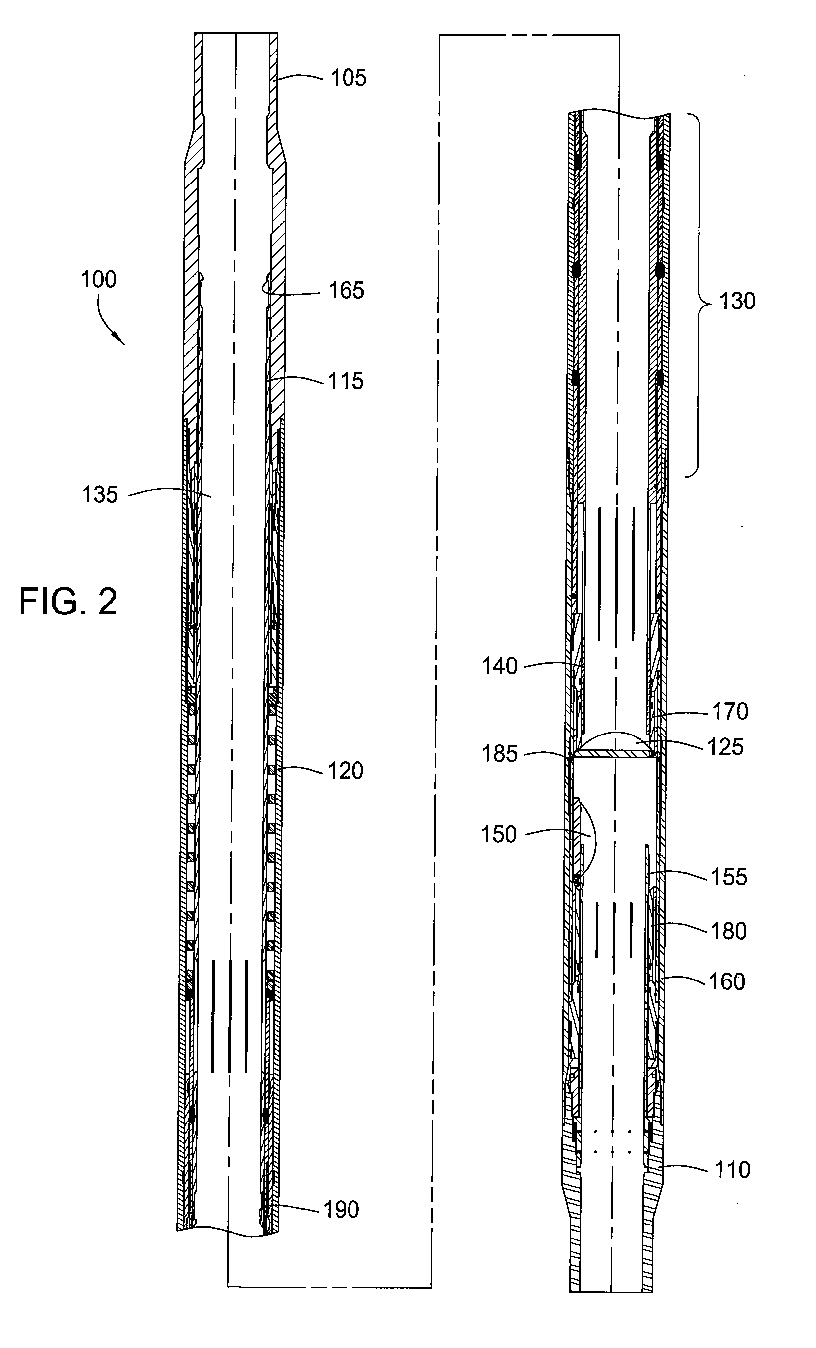
[0020]The tool 100 includes a first flapper valve 125 and a second flapper valve 150. The valves 125, 150 are movable between an open position and a closed position multiple times. As shown in FIG. 1, the valves 125, 150 are in the open position when the tool 100 is run into the wellbore. Generally, the valves 125, 150 are used to open and close a bore 135 of the tool 100 in order to selectively isolate a portion of the wellbore above the tool 100 from a portion of the wellbore below the ...


PUM


Abstract

The present invention generally relates to a wellbore tool for selectively isolating a portion of a wellbore from another portion of the wellbore. In one aspect, a method of selectively isolating a zone in a wellbore is provided. The method includes the step of positioning a downhole tool in the wellbore. The downhole tool includes a bore with a first flapper member and a second flapper member disposed therein, whereby each flapper member is initially in an open position. The method also includes the step of moving the first flapper member to a closed position by rotating the first flapper member in one direction. Further, the method includes the step of moving the second flapper member to a closed position by rotating the second flapper member in an opposite direction, whereby each flapper member is movable between the open position and the closed position multiple times. In another aspect, an apparatus for isolating a zone in a wellbore is provided.

Description

CROSS-REFERENCE TO RELATED APPLICATIONS[0001]This application claims benefit of U.S. provisional patent application Ser. No. 60 / 804,547, filed Jun. 12, 2006, which is herein incorporated by reference in its entirety.BACKGROUND OF THE INVENTION[0002]1. Field of the Invention[0003]Embodiments of the present invention generally relate to wellbore completion. More particularly, the invention relates to a wellbore tool for selectively isolating a zone in a wellbore.[0004]2. Description of the Related Art[0005]A completion operation typically occurs during the life of a well in order to allow access to hydrocarbon reservoirs at various elevations. Completion operations may include pressure testing tubing, setting a packer, activating safety valves or manipulating sliding sleeves. In certain situations, it may be desirable to isolate a portion of the completion assembly from another portion of the completion assembly in order to perform the completion operation. Typically, a ball valve, wh...

Claims


Application Information

Patent Timeline
Patent Type & Authority Applications(United States)
IPC IPC(8): E21B34/14E21B34/08
CPCE21B34/066E21B2034/005E21B34/101E21B34/10E21B2200/05E21B34/06
Inventor JACKSON, STEPHEN L.FOSTER, MICHAEL
Owner WEATHERFORD TECH HLDG LLC
Why Eureka
Try Eureka