Method and device for detecting initial excitation phase of stepping motor

a technology of excitation phase and stepping motor, which is applied in the direction of dynamo-electric converter control, programme control, instruments, etc., can solve the problems of insufficient method, complex mechanism, and different amount of movement of pointers (or indicators) moving in accordance with rotation of stepping motors

Active Publication Date: 2007-12-27
YAZAKI CORP
View PDF3 Cites 5 Cited by
  • Summary
  • Abstract
  • Description
  • Claims
  • Application Information

AI Technical Summary

Benefits of technology

[0012]It is therefore an objective of the present invention to solve the above problems and to provide a method and device for detecting an initial excitation phase of a stepping motor, by which the initial excitation phase can be detected with a pitch angle finer than a pitch angle of one phase excitation without using elements such as magnetoelectric elements that cause cost-up or complication in the mechanism.
[0034]With the construction described above, in order to judge whether or not the rotor rotates during the full step drive of the stepping motor, in the exciting of the stepping motor in the third step or by the third exciting means, when the stepping motor is subjected to the full step drive in the positive or reverse rotation direction of the rotor, the excitation phase of the stepping motor is once changed from the third excitation phase that is not the excitation phase upon the full step drive to the first excitation phase that is the excitation phase upon the full step drive, thereby preventing the subsequent excitation phase of the full step drive of the stepping motor from shifting.

Problems solved by technology

However, as for a vehicle in which an on-vehicle meter using such a stepping motor is mounted, by an incorrect drive signal generated due to vehicle vibrations or noises, there might be a problem that an actual amount of movement of a pointer (or indicator) moving in accordance with rotation of the stepping motor is different from an amount of movement thereof, which is originally expected.
However, the method using the magnetoelectric elements results in cost-up or a problem that the mechanism becomes complicated due to limitation of the placing position in the proximity of the rotor or deterioration in reliability in a case of avoiding such a limitation.
The detection by using the exciting coil in a non-excitation state has a problem that the initial excitation phase can be specified only with a pitch angle of one phase excitation due to a limited detection timing obtained only upon full step driving, therefore the method is not sufficient as a method of detecting the initial excitation phase of the stepping motor of a micro-step drive.

Method used


Image

  • Method and device for detecting initial excitation phase of stepping motor
  • Method and device for detecting initial excitation phase of stepping motor
  • Method and device for detecting initial excitation phase of stepping motor

Examples


Embodiment Construction

[0060]In the following, the preferred embodiments of the present invention will be explained with reference to the attached drawings.

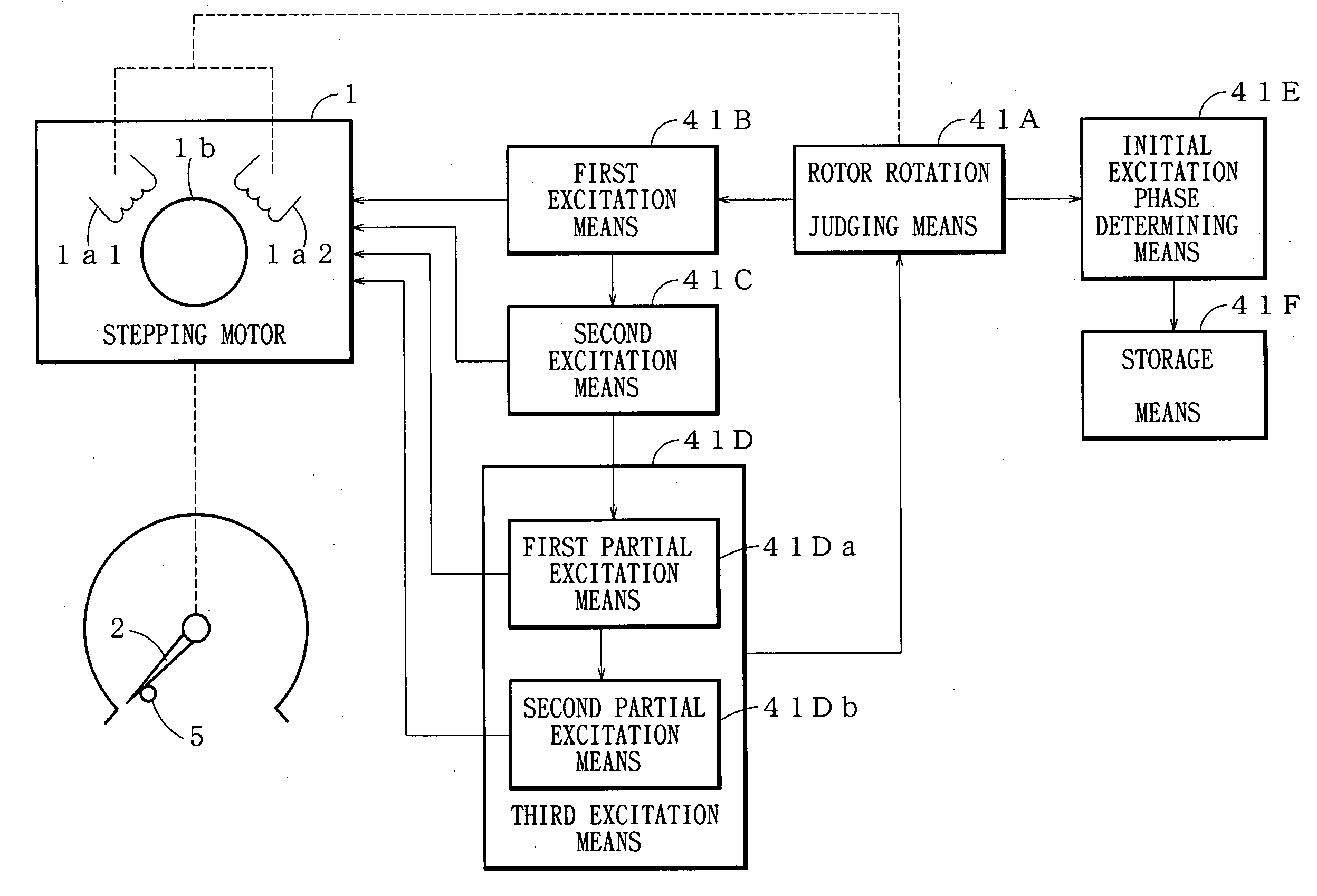
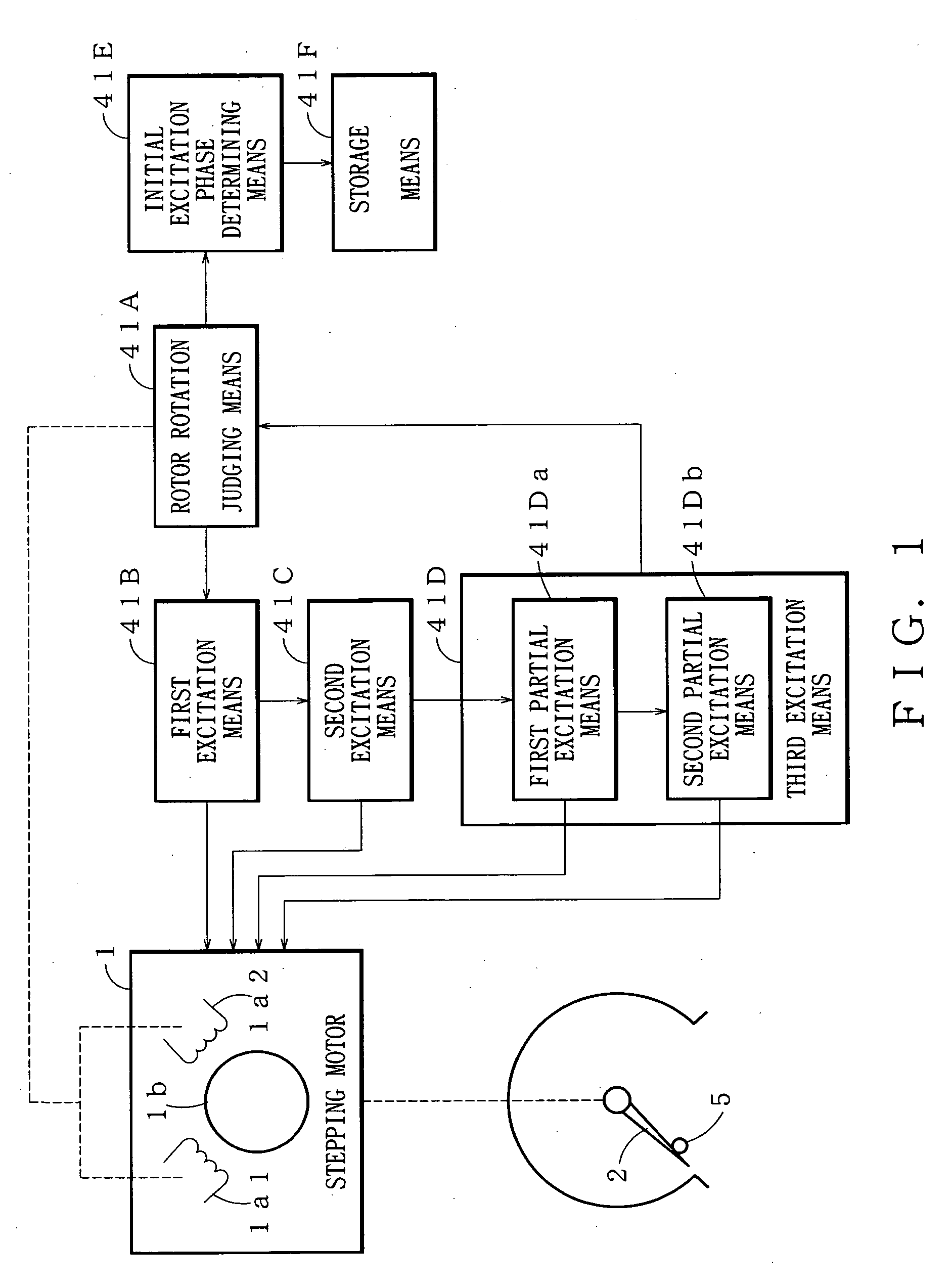
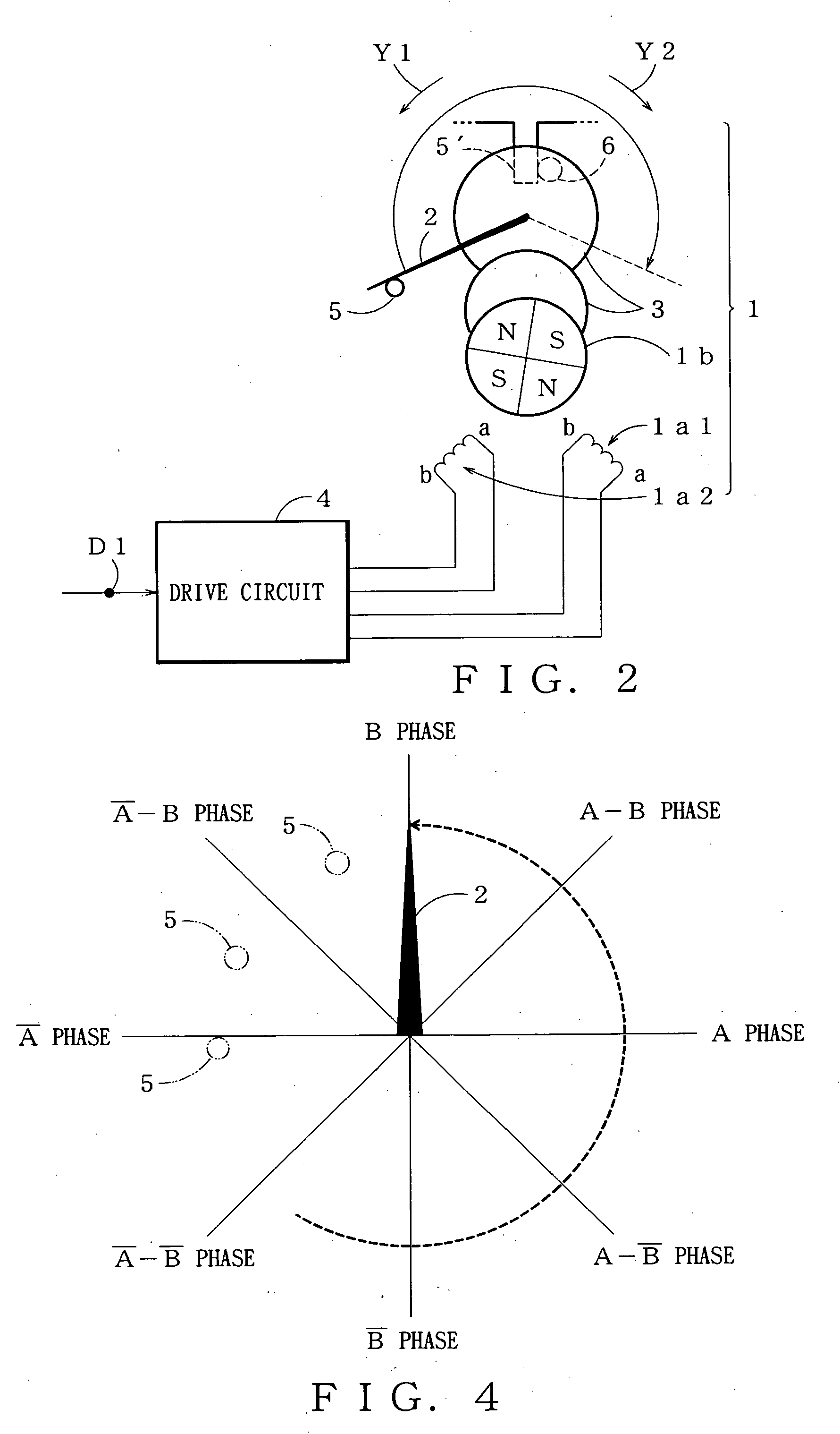
[0061]FIG. 2 shows a construction of an on-vehicle meter to which the present invention is applied. The on-vehicle meter is, for example, a speed meter including: two exciting coils (i.e. magnetizing coils) 1a1 and 1a2 wound up around respective stators (not shown in the figure) arranged crossing at right angles to each other; a stepping motor 1 having a rotor 1b which rotates in response to a change in an excitation state (i.e. magnetization state) of the exciting coils 1a1 and 1a2; and a drive circuit 4 for driving the stepping motor 1.

[0062]The on-vehicle meter further includes: a pointer 2 as a driven member which moves in response to a rotation drive of the rotor 1b; a gear 3 for transmitting the rotation drive of the rotor 1b to the pointer 2; and a stopper 5 which allows the pointer 2 to come in contact with the stopper 5 at a mechanical zero po...


PUM


Abstract

A method and device for detecting an initial excitation phase of a stepping motor is provided, by which an initial excitation phase of a rotor corresponding to a position of a stopper can be detected with a unit of a stepping angle of a microstep drive which is smaller than that of a full step drive without using elements such as magnetoelectric elements. Upon appropriately changing an excitation phase of a stepping motor, on the basis of a generated pattern of an induced electromotive force in an exciting coil in a non-excitation state upon a full step drive, whether or not a pointer comes in contact with a stopper to stop a reverse rotation of the pointer and rotor is judged so that it is specified on which excitation phase the pointer and rotor are reversed, thereby detecting an initial excitation phase of the rotor corresponding to a position of the stopper.

Description

BACKGROUND OF THE INVENTION[0001](1) Field of the Invention[0002]The present invention relates to a method and device for detecting an initial excitation phase of a stepping motor, wherein the initial excitation phase in which a rotor of the stepping motor is stable is detected at a stop position where a reverse rotation of a driven member driven by the stepping motor is forcedly stopped by a stopper.[0003](2) Description of the Related Art[0004]Recently, a stepping motor has been often used for an on-vehicle meter such as a speed meter or tachometer in terms of indicating accuracy and cost.[0005]However, as for a vehicle in which an on-vehicle meter using such a stepping motor is mounted, by an incorrect drive signal generated due to vehicle vibrations or noises, there might be a problem that an actual amount of movement of a pointer (or indicator) moving in accordance with rotation of the stepping motor is different from an amount of movement thereof, which is originally expected....

Claims


Application Information

Patent Timeline
Patent Type & Authority Applications(United States)
IPC IPC(8): H02P8/00
CPCH02P8/08G01R7/06G01D2213/10
Inventor TORIKOSHI, AKIHIKO
Owner YAZAKI CORP
Why Eureka
Try Eureka