Optical fiber transition device

a technology of optical fiber and transition device, which is applied in the direction of optics, fibre mechanical structure, instruments, etc., can solve the problems of degrading the quality of optical transmission, and achieve the effect of reducing the amount of excess cable length and minimizing cable slack storag

Inactive Publication Date: 2008-01-17
CORNING OPTICAL COMM LLC
View PDF11 Cites 23 Cited by
  • Summary
  • Abstract
  • Description
  • Claims
  • Application Information

AI Technical Summary

Benefits of technology

[0011] Another aspect of the present invention is the ability for a field installer to customize the cable length for each particular application. Rather than using predetermined cable lengths with connectors already installed on each end of the optical fiber cable, the present invention provides a pigtail-type optical fiber cable where one end of the optical fiber cable is provided with a factory-installed connector and the other end may be reduced to a desired length. This significantly reduces the amount of excess cable length, and therefore minimizes cable slack storage, without requiring a large number of different length cables to be at the installer's disposal for field installation.

Problems solved by technology

Exposing the optical fiber to the outside environment introduces serious risks of damaging the optical fiber and introducing microbends in the optical fiber that may significantly degrade the quality of optical transmission.

Method used


Image

  • Optical fiber transition device
  • Optical fiber transition device
  • Optical fiber transition device

Examples


Embodiment Construction

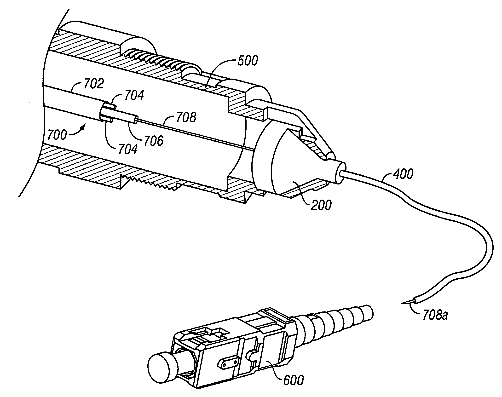
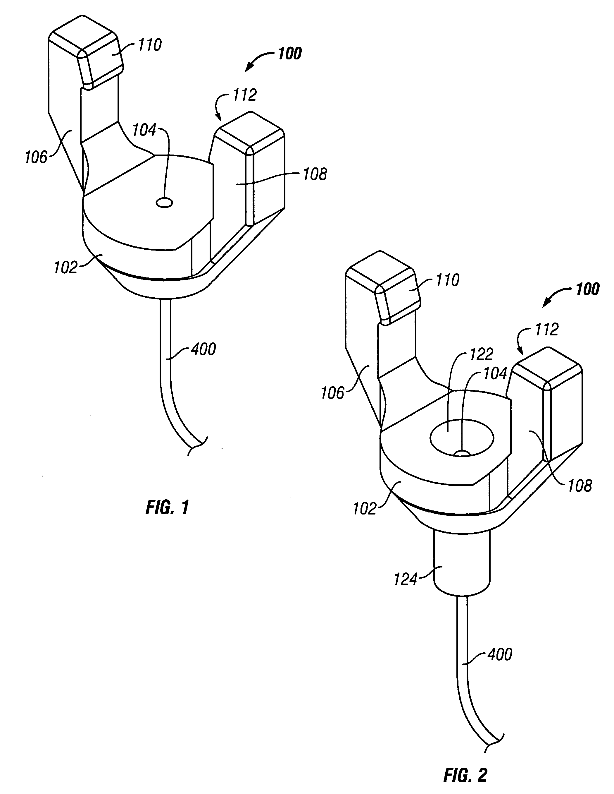
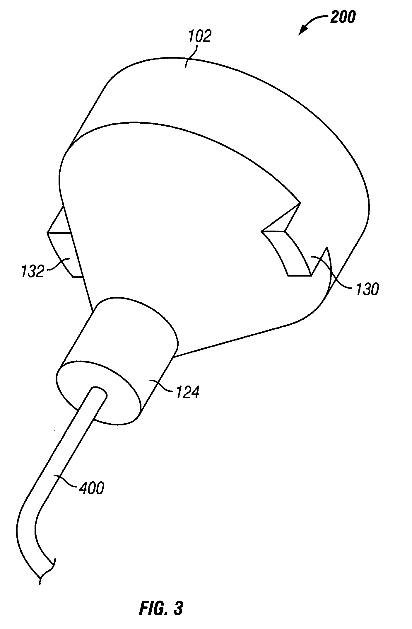
[0029] Reference will now be made in greater detail to various exemplary embodiments of the invention, preferred embodiments of which are illustrated in the accompanying drawings. Whenever possible, the same reference numerals will be used throughout the drawings to refer to the same or similar parts. A single fiber field-installable mechanical splice connector operable for terminating a field optical fiber to a connector is shown herein for use with the various embodiments of the invention merely for purposes of convenience. It should be understood, however, that the apparatus and methods for transitioning an optical fiber of a fiber optic cable to an optical connector disclosed herein may be applied to any optical coupling between any number of optical fibers, such as, but not limited to, any optical connection between one or more adjoining optical fibers. Accordingly, the invention should not be construed as being limited in any manner by the particular example of a single fiber ...


PUM


Abstract

The present invention addresses the need for a stress relieving device and protective jacket for exposed fiber within a field-installed optical network enclosure, such as a network interface device. The present invention incorporates a furcation tube coupled with a furcation body. The coupling may be accomplished by a direct connection or with use of an external or internal transition body. The present invention enables a field-installer to transition an optical fiber cable from the field into a furcation tube thereby providing a means for attaching an optical connector, such as a mechanical splice connector, onto the optical fiber and furcation tube.

Description

BACKGROUND OF THE INVENTION [0001] 1. Field of the Invention [0002] The present invention relates generally to a transition device for an optical network enclosure allowing for the transition of an optical fiber contained within an optical fiber cable into a furcation tube thereby providing strain relief, protection of the optical fiber, and a means for attaching a field-installable optical connector. [0003] 2. Technical Background [0004] Optical fibers are widely used in a variety of applications, including the telecommunications industry which utilizes optical fibers in a number of telephone and data transmission applications. The extremely wide bandwidth and low noise operation provided by optical fibers naturally leads to a broad range of possible uses, and the variety of applications in which optical fibers are utilized continues to grow. For example, optical fibers no longer serve as merely a medium for long distance signal transmission, but are being increasingly routed direc...

Claims


Application Information

Patent Timeline
Patent Type & Authority Applications(United States)
IPC IPC(8): G02B6/36
CPCG02B6/3801G02B6/4471G02B6/3887G02B6/3846G02B6/4478
Inventor BARNES, BRANDON A.BILLMAN, BRADLEY S.KERR, SEAN M.RAKER, JOSHUA D.YOW, CHARLES A. JR.
Owner CORNING OPTICAL COMM LLC
Why Eureka
Try Eureka