Aerogel insulation systems for pipelines

a technology of pipelines and aerogel, which is applied in the field of materials packaging, can solve the problems of less efficient time-consuming and laborious process, and negatively affecting the thermal performance of the insulation, so as to maximize the packing out for shipping, reduce installation labor, and increase efficiency

Inactive Publication Date: 2008-01-17
ASPEN AEROGELS INC
View PDF14 Cites 19 Cited by
  • Summary
  • Abstract
  • Description
  • Claims
  • Application Information

AI Technical Summary

Benefits of technology

[0016]The invention has a number of advantages over prior methods in this area, some of which are noted here. The invention maximizes pack-out for shipping, and also minimizes installation labor, both of which may increase efficiency and lower cost. In embodiments where vacuum is applied prior to shipping, the need for doing so on-site can be eliminated. The invention allows for exacting preparation of the proper geometry, and thus minimizes film waste, and can eliminate the need for additional materials, such as adhesive, which can have adverse effects on insulation thermal conductivity.

Problems solved by technology

Pipes insulated in the oil and gas industry may be a mile, several miles, or more in length, thus this can be a time-consuming and labor intensive process.
This configuration may permit faster installation by the end-user, but the introduction of adhesive can negatively affect thermal performance of the insulation, and the circular shape of the pre-formed package results in less efficient pack-out for shipping.
Shapeable vacuum-sealed insulation is known (e.g., US Patent Publication No. 20060035054), but it is not prepared in a manner allowing both efficient pack-out for shipping and efficient pre-calculated shaping.

Method used


Image

  • Aerogel insulation systems for pipelines
  • Aerogel insulation systems for pipelines
  • Aerogel insulation systems for pipelines

Examples


embodiments

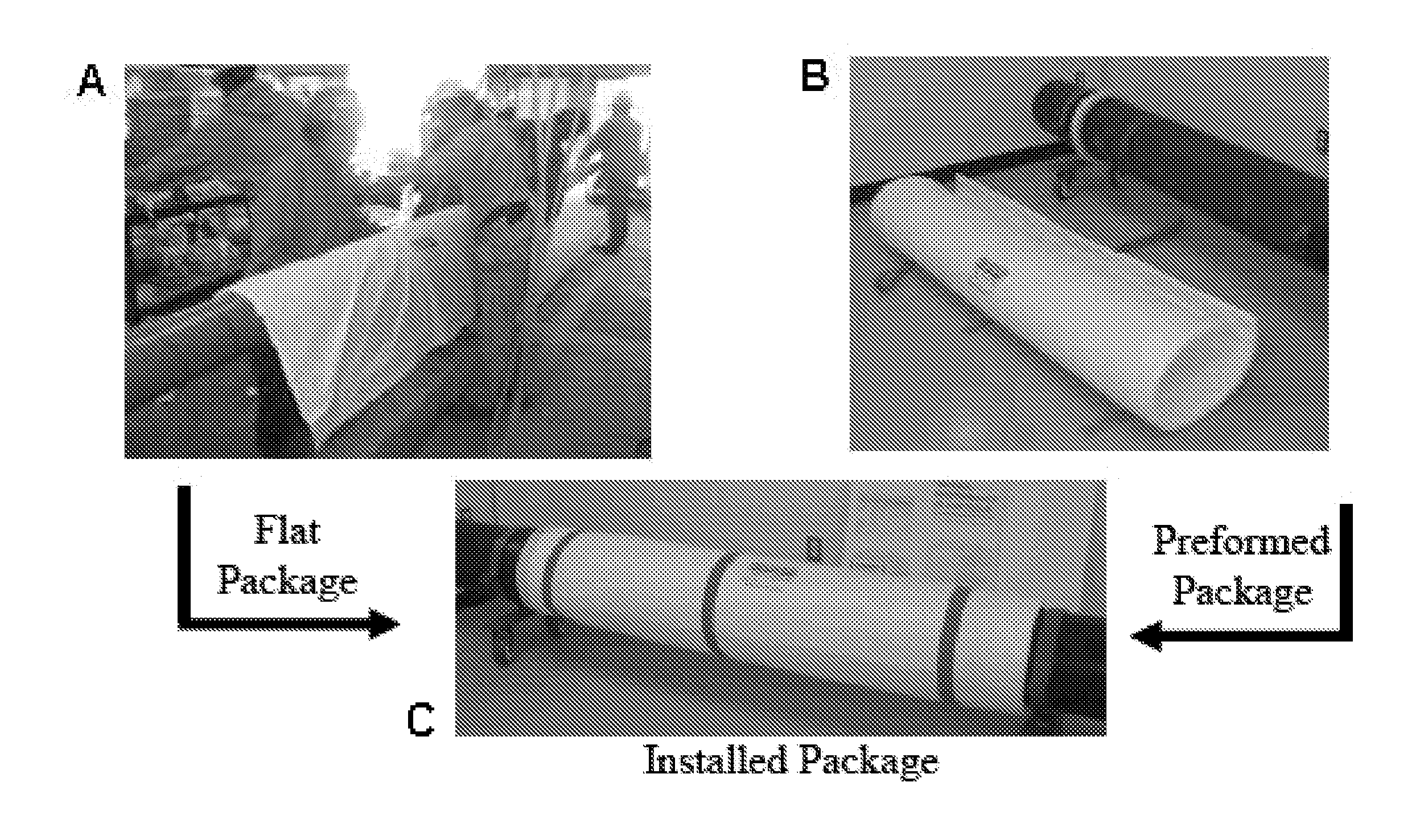
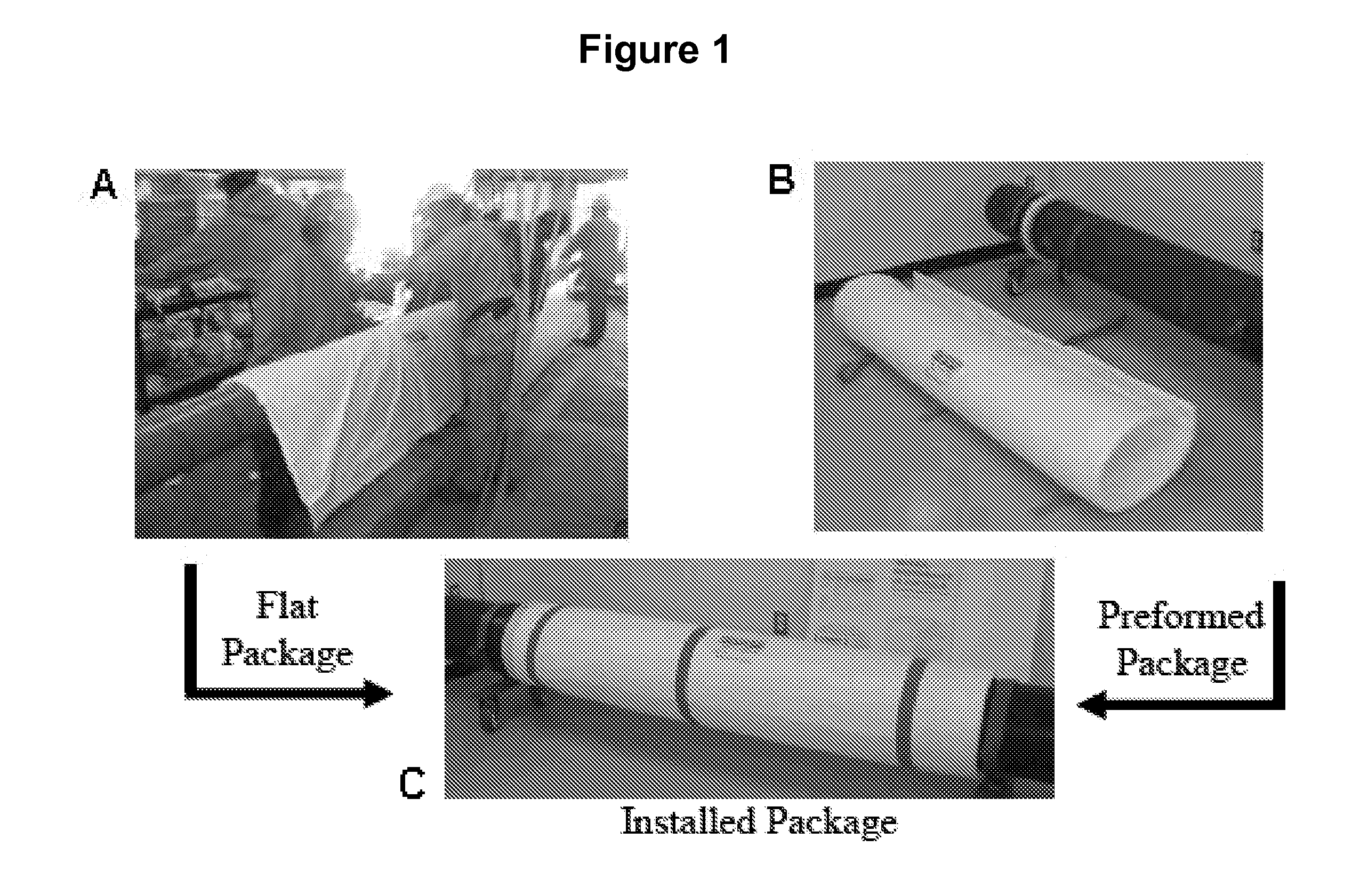
[0065]Embodiments of this invention describe a method for forming a package with 3D, annular geometry, such that the package is fabricated and / or shipped in a flat state and curvature, preferably annular geometry, can be later imparted to the packaged material via the application of heat. The packaging, termed herein a “smart-bag,” is made of two heat-shrinkable films. The films have different elongation or shrinkage properties such that when heat is applied, the films elongate or shrink to impart curvature to the flat package contents. For example, two films may be used to package an insulation material for installation around a pipe. One film, intended to be in contact with the outer surface of the pipe, shrinks to a shorter circumferential length than the other film representing the insulation “outer surface” that would be present subsequent to installation of the package. This difference in shrinkage causes curvature to be imparted to the package, thus assisting in the installat...

example 1

Imparting Curvature to Flat Insulation

[0092]Two pieces of heat shrinkable film of different shrinkage properties were placed around a 12″×12″×¼″ flat sheet of aerogel and heat sealed around the edges. A heat source was applied to the film, which shrank and imparted curvature to the otherwise flat, bagged piece of insulation.

example 2

Design of a Smart Bag to Contain Insulation for Installation on an Oil Pipeline

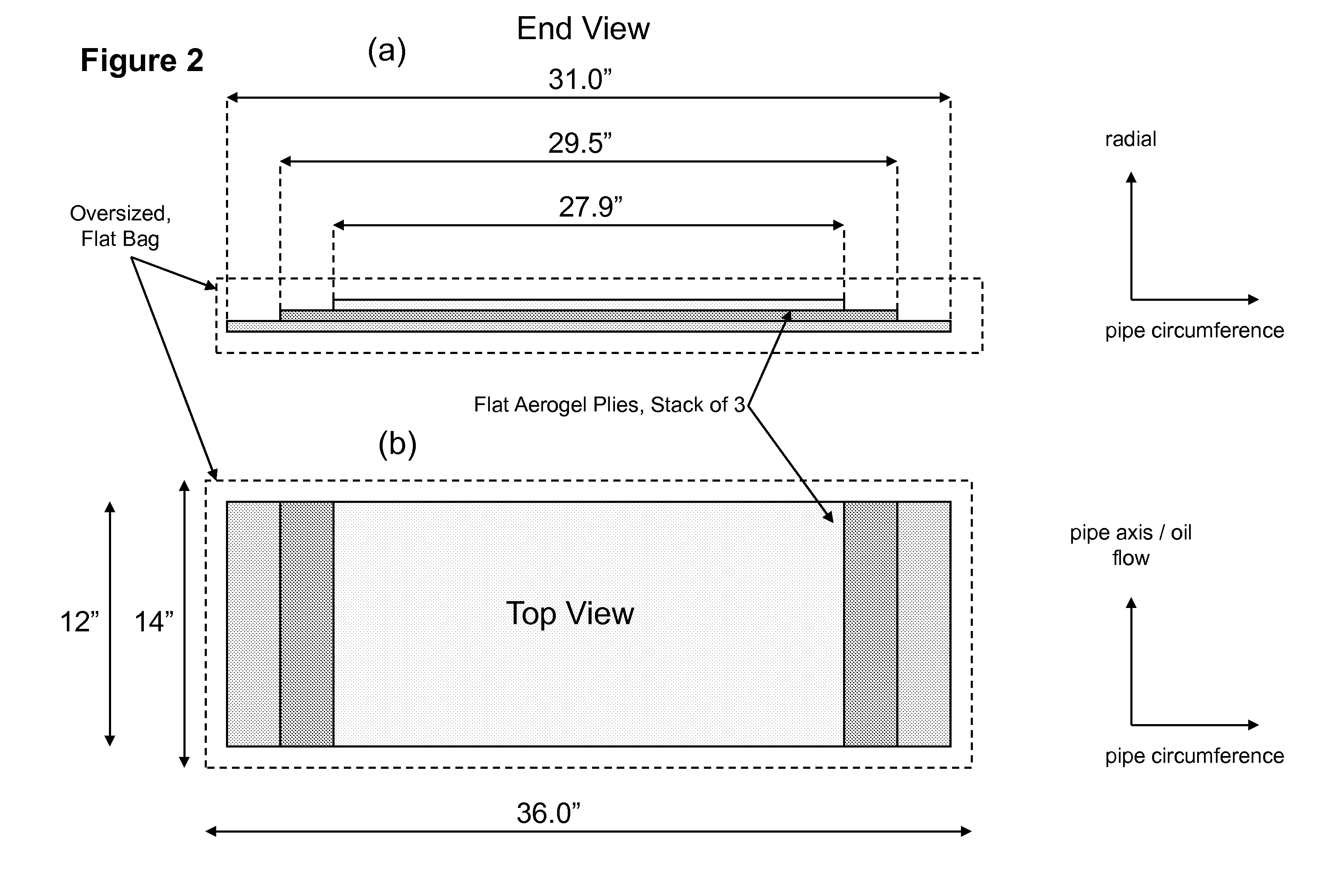
[0093]Given a pipeline with an outer diameter of 8.625″ and three planar sheets, each 0.25″ thick, of aerogel blanket with fibrous batting (see US Patent Publication No. 20020094426) that would give 0.75″ of total insulation thickness after stacking, and that are cut to lengths permitting the formation of a closed annular geometry after being curved for fitting around the pipeline (see FIG. 2), initial dimensions are proposed for a smart bag. With the ply stack-up of FIG. 2 measuring 31″×12″×0.25″ for the largest ply, and planning a slightly oversize bag to place the insulation into, the smart bag is initially proposed to measure 36″×16″.

[0094]The dimensions having been determined, a shrinkage calculation is performed by calculating the dimensions for a package with annular geometry, an inner package circumference to match the pipeline's outer circumference, and an outer package circumference taking in to...


PUM

PropertyMeasurementUnit
pressureaaaaaaaaaa
pressureaaaaaaaaaa
pressureaaaaaaaaaa

Abstract

The invention provides a method for imparting curvature to a substantially planar material comprising placing substantially planar material in a smart bag, and heat shrinking the smart-bagged material, wherein curvature is imparted to the smart-bagged material upon heat-shrinkage (e.g., placing an aerogel blanket with fibrous batting in a smart bag, applying vacuum and sealing the bag, shipping the flat bagged material to a work-site, heat-shrinking the bag to impart annular geometry, and securing the bagged insulation around an oil pipeline). Methods are included for preparing a smart bag of the invention.

Description

CROSS-REFERENCES TO RELATED APPLICATIONS[0001]This application claims benefit of priority from U.S. Provisional Patent Applications 60 / 807,575 filed Jul. 17, 2006 which is incorporated herein by reference in its entirety as if fully set forthFIELD OF THE INVENTION[0002]The invention generally relates to packaging of materials to permit imparting of curvature to the material prior to use, for example, for packaging and installation of insulation around pipes, such as in an oil pipeline or liquid natural gas pipeline.DESCRIPTION[0003]Current methods of encapsulating insulation for use, such as on oil pipelines, include both flat and “pre-formed” packages. In the former example, flat layers of insulation may be encapsulated in a bagging material, such as Tyvek®, and manually wrapped around a circular pipeline (FIG. 1, A). Low emissivity foil may be added, and the pipeline then pushed into an outer protective pipe. Pipes insulated in the oil and gas industry may be a mile, several miles...

Claims


Application Information

Patent Timeline
Patent Type & Authority Applications(United States)
IPC IPC(8): B32B1/04
CPCB29C53/025B29C53/04Y10T428/25B32B3/04Y10T428/239B29C61/006F16L59/026F16L59/04F16L59/06F16L59/065F16L59/08Y10T428/31743B32B2305/08B32B27/12B32B27/08B32B2307/304B32B1/08B32B2307/736B32B2309/12B32B2597/00
Inventor TOMICH, AARON R.
Owner ASPEN AEROGELS INC
Why Eureka
Try Eureka