Electromagnetically Driven Valve

Inactive Publication Date: 2008-02-07
TOYOTA JIDOSHA KK
View PDF11 Cites 0 Cited by
  • Summary
  • Abstract
  • Description
  • Claims
  • Application Information

AI Technical Summary

Benefits of technology

[0009] According to the electromagnetically driven valve structured as above, the fix portion is provided, so that the torsion spring is attached to the supporting member with a phase angle around the axis extending at the other end being adjusted, and fixed to that position. Accordingly, the spring load imposed by the torsion spring onto the oscillating member can accurately be set to a value determined in design. Here, when the oscillating member actually oscillates, no error is produced between the spring load imposed by the torsion spring onto the oscillating member and the spring load calculated in design. Therefore, electromagnetic force based on the spring load in design is applied to the oscillating member, whereby stable reciprocating motion of the driven valve is achieved. As it is not necessary to apply the electromagnetic force for eliminating the error in the spring load, waste of electric power in the electromagnetically driven valve can be prevented.
[0010] Preferably, a plurality of oscillating members are provided, with a distance from each other in a direction in which the valve shaft extends. According to the electromagnetically driven valve structured as above, an effect as described above can be obtained in the electromagnetically driven valve adopting a parallel link mechanism.
[0011] Preferably, the fix portion includes an outer circumferential surface of the torsion spring, having serration formed. The supporting member has an opening for receiving the fix portion. An inner wall of the opening has serration formed, which is engaged with the serration formed on the fix portion. According to the electromagnetically driven valve structured as above, engagement between the serration formed on the outer circumferential surface of the torsion spring and the serration formed on the inner wall of the opening is shifted, so that a phase angle of the torsion spring around the axis with respect to the supporting member can be adjusted. In addition, as engagement between the serrations is strong, the torsion spring can further reliably be fixed in the adjusted position.
[0012] Preferably, t

Problems solved by technology

On the other hand, in the torsion bar and the helical spring, error in shape inevitable in the manufacturing step or assembly error with respect to the disc support base or the stem is produced, which results in failure in accurate setting of the disc to the intermediate position.
In such a case, error in spring load imposed on the dr

Method used


Image

  • Electromagnetically Driven Valve
  • Electromagnetically Driven Valve
  • Electromagnetically Driven Valve

Examples


first embodiment

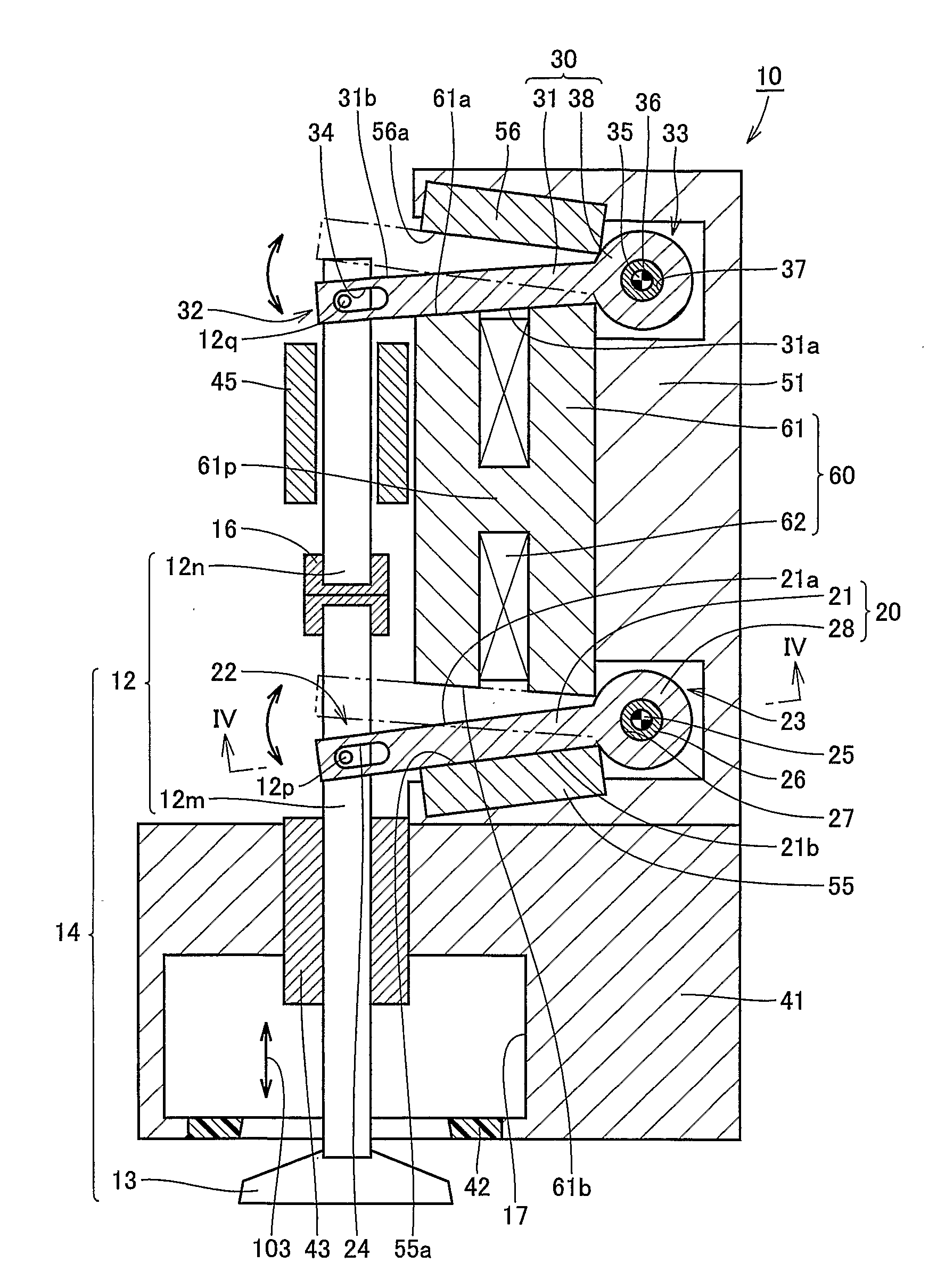
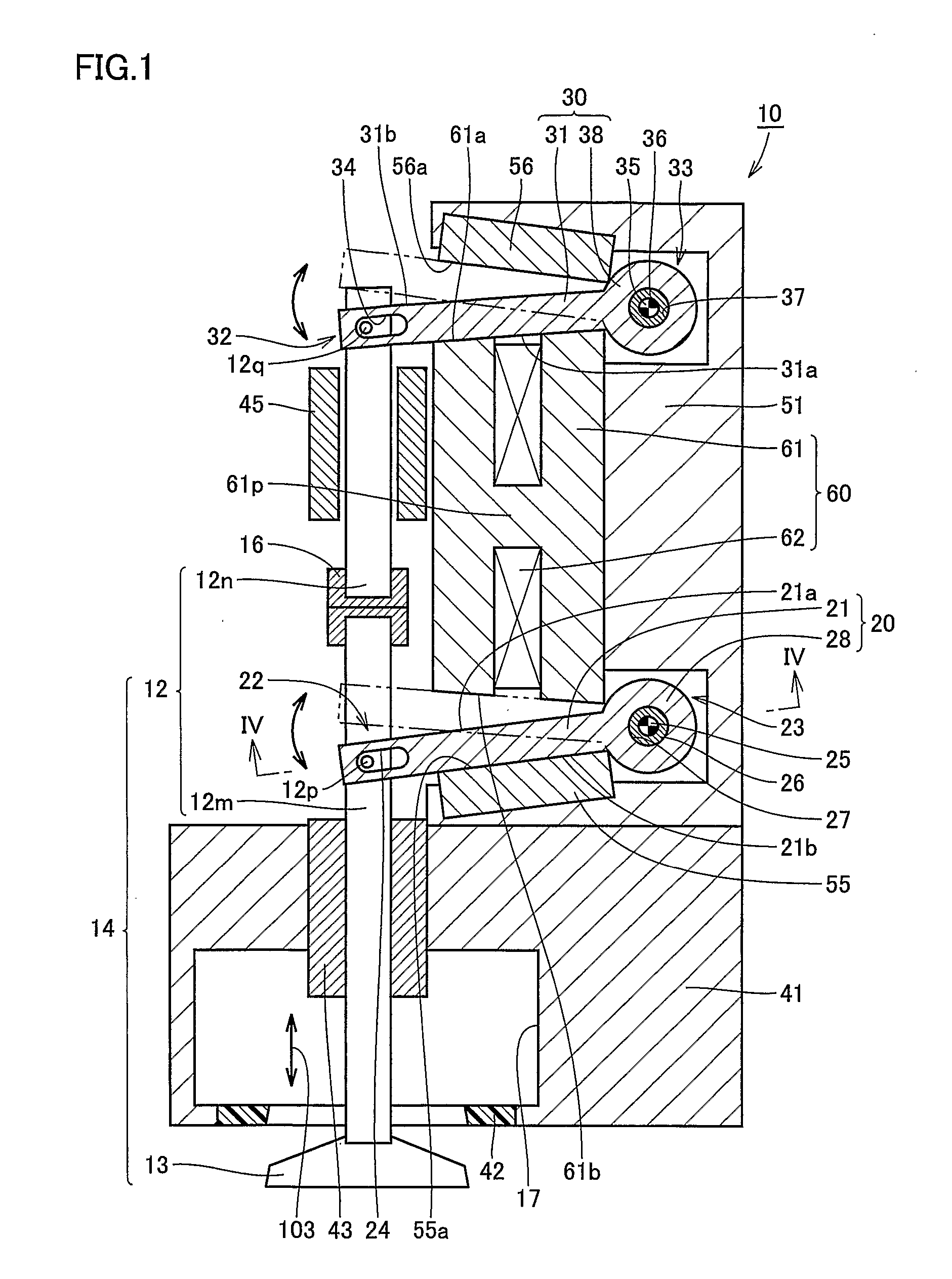
[0030] The electromagnetically driven valve according to the present embodiment implements an engine valve (an intake valve or an exhaust valve) in an internal combustion engine such as a gasoline engine or a diesel engine. In the present embodiment, description will be given assuming that the electromagnetically driven valve implements an intake valve, however, it is noted that the electromagnetically driven valve is similarly structured also when it implements an exhaust valve.

[0031] Referring to FIG. 1, an electromagnetically driven valve 10 is a rotary drive type electromagnetically driven valve. As an operation mechanism for the electromagnetically driven valve, a parallel link mechanism is applied.

[0032] Electromagnetically driven valve 10 includes a driven valve 14 having a stem 12 extending in one direction, a lower disc 20 and an upper disc 30 coupled to different positions on stem 12 and oscillating by receiving electromagnetic force and elastic force applied thereto, a ...

second embodiment

[0060] An electromagnetically driven valve according to the present embodiment is structured in a manner basically similar to electromagnetically driven valve 10 in the first embodiment. Therefore, description of a redundant structure will not be repeated.

[0061]FIG. 11 shows a region similar to that shown in FIG. 5. Referring to FIG. 11, in the present embodiment, outer circumferential surface 4a of fix portion 4 is formed as a tapered surface. In other words, outer circumferential surface 4a extends in a manner inclined with respect to central axis 25, and is implemented by a side surface of a frustum of a cone formed along central axis 25. On the inner wall of opening 52, a tapered surface being in surface contact with outer circumferential surface 4a while lower torsion bar 26 is inserted in opening 52 is formed. Fix portion 4 has a hexagonal hole 84 formed from a side of an end surface 4c of fix portion 4.

[0062] Disc support base 51 has a female screw hole 81 formed, which is ...

third embodiment

[0069] An electromagnetically driven valve according to the present embodiment is structured in a manner basically similar to electromagnetically driven valve 10 in the first embodiment. Therefore, description of a redundant structure will not be repeated.

[0070]FIG. 13 shows a region similar to that shown in FIG. 5. Referring to FIG. 13, in the present embodiment, outer circumferential surface 4a of fix portion 4 has a male screw formed. Fix portion 4 has a hexagonal hole 88 formed from a side of end surface 4c of fix portion 4. On the other hand, the inner wall of opening 52 has a female screw formed, into which a male screw formed on outer circumferential surface 4a is screwed. A locknut 86 is fastened to opening 52 from a side opposite to fix portion 4, and end surface 4c of fix portion 4 is pressed by an end surface 86c of locknut 86 facing end surface 4c. Locknut 86 has a hole 87 formed, which is penetrated in a direction in which central axis 25 extends.

[0071] The step of ad...


PUM


Abstract

An electromagnetically driven valve includes a driven valve having a stem and carrying out reciprocating motion along a direction in which the stem extends, a disc support base, a lower disc having one end coupled to the stem and the other end supported by the disc support base so as to allow free oscillation of the lower disc and oscillating around a central axis extending at the other end, and a lower torsion bar provided so as to extend along the central axis and fixed to the other end. The lower torsion bar has a fix portion fixed to the disc support base, and a phase angle thereof around the central axis with respect to the disc support base can be adjusted. With such a structure, the driven valve can carry out reciprocating motion in a stable manner, and energy loss can be reduced.

Description

TECHNICAL FIELD [0001] The present invention generally relates to an electromagnetically driven valve, and more particularly to an electromagnetically driven valve of a rotary drive type used in an internal combustion engine and driven by electromagnetic force and elastic force. BACKGROUND ART [0002] Japanese Utility Model Laying-Open No. 61-200919 discloses a knock pin having serration formed on an outer circumferential surface of a pin body along an axial direction thereof In addition, Japanese Utility Model Laying-Open No. 61-200920 discloses a knock pin having an elastic body provided on an outer circumferential surface of a pin body, the elastic body being pressed against and brought in contact with a wall surface of an insertion hole. [0003] Japanese Utility Model Publication No. 14-20004 discloses an apparatus for preventing loosening of a male screw, which includes a male screw threaded on an outer circumference and having a notch in a part of the outer circumference, and a ...

Claims


Application Information

Patent Timeline
IPC IPC(8): F01L9/04F16K31/06
CPCF16K31/0682F01L2009/2109
Inventor ASANO, MASAHIKOSUGIE, YUTAKA
Owner TOYOTA JIDOSHA KK
Why Eureka
Try Eureka