
Bandgap reference circuit and sensor chip using the same

Active Publication Date: 2018-11-01
PIXART IMAGING INC
View PDF13 Cites 5 Cited by
  • Summary
  • Abstract
  • Description
  • Claims
  • Application Information

AI Technical Summary

Benefits of technology

The present disclosure relates to a bandgap reference circuit that is designed to reduce power consumption and improve accuracy in the setting of a reference voltage. The circuit is able to shut down or pause the use of the bandgap reference voltage source and the regulator in a low power mode or suspend mode to significantly reduce power consumption. The source voltage is also more accurately set and has lower variations in a suspend mode, which allows for a lower level of voltage arrangement to reduce leakage current. Furthermore, the calibration on the source voltage is automatically accomplished in the normal mode, eliminating the need for wafer or chip level trimming to effectively reduce costs during testing and production.

Problems solved by technology

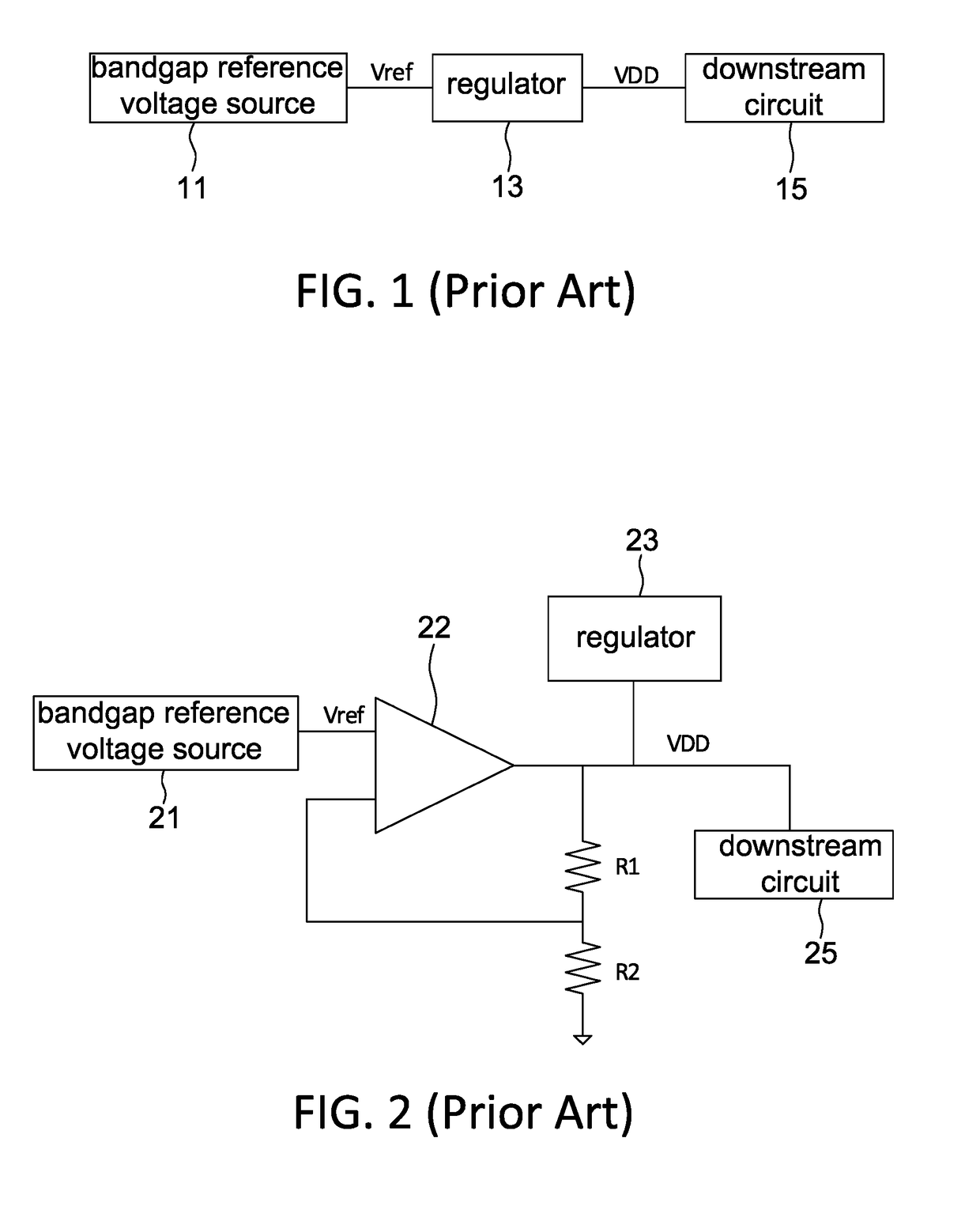
However, in a lower power mode, the regulator 13 still requires the power continuously provided by the bandgap reference voltage source 11 to generate the source voltage VDD, such that significant power is still consumed in the low power mode.
However, it is not easy to achieve this purpose because when the bandgap reference voltage source for providing an accurate reference voltage Vref is shut down and if the reference voltage Vref has a 10% voltage variation, the source voltage VDD provided by the clamp circuit may change more than 10% to exceed the allowable working voltage range.

Method used


Image

  • Bandgap reference circuit and sensor chip using the same
  • Bandgap reference circuit and sensor chip using the same
  • Bandgap reference circuit and sensor chip using the same

Examples


Embodiment Construction

[0042]It should be noted that, wherever possible, the same reference numbers will be used throughout the drawings to refer to the same or like parts.

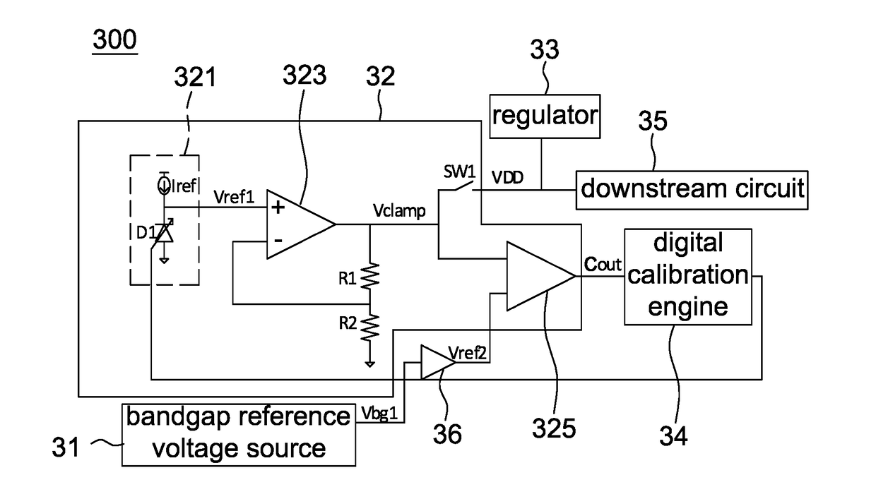
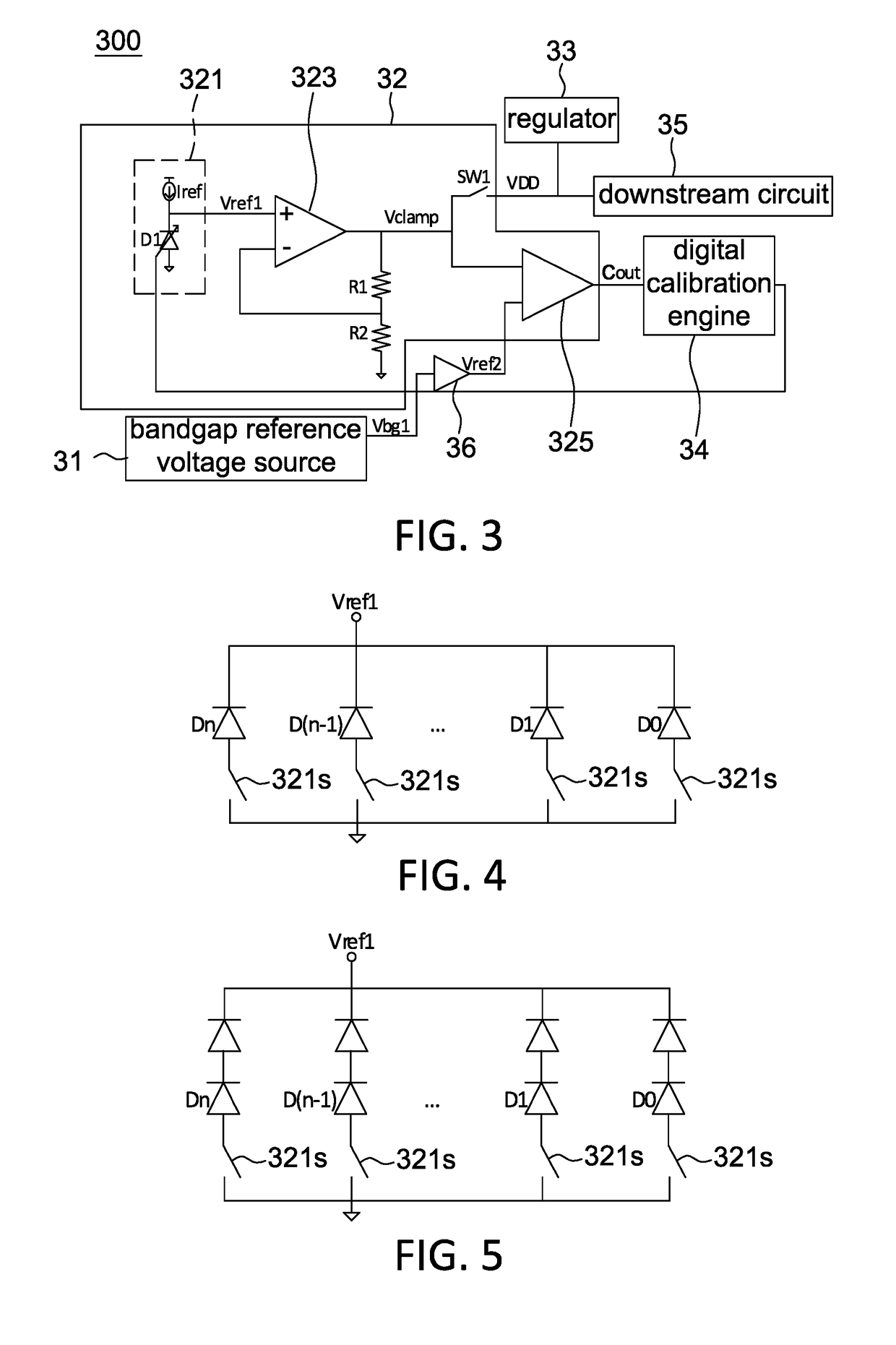
[0043]Referring to FIG. 3, it is a block diagram of a bandgap reference circuit 300 according to one embodiment of the present disclosure. The bandgap reference circuit 300 includes a bandgap reference voltage source 31, a clamp circuit 32, a regulator 33 and a digital calibration engine 34. The bandgap reference circuit 300 is used to provide a source voltage VDD to a downstream circuit 35, wherein the downstream circuit 35 includes, for example, a digital core. The source voltage VDD is, for example, smaller than or equal to 1 volt, but not limited to. If the calibration is performed properly, the source voltage VDD may be set at a lower voltage level.

[0044]In the embodiment of the present disclosure, as the calibrated clamp voltage Vclamp outputted by the clamp circuit 32 is almost equal to the desired source voltage VDD and has a sm...


PUM


Abstract

A bandgap reference circuit including a clamp circuit is provided. The bandgap reference circuit performs the calibration only for one time in a normal mode to store a control code of a reference generator of the clamp circuit. In a suspend mode, the control code is used for controlling the reference generator to cause the clamp circuit to provide a desired source voltage, and a bandgap reference voltage source is shut down to reduce the power consumption.

Description

RELATED APPLICATIONS[0001]The present application is a continuation-in-part application of U.S. patent application Ser. No. 15 / 499,497 filed on Apr. 27, 2017, the disclosure of which is hereby incorporated by reference herein in its entirety.BACKGROUND1. Field of the Disclosure[0002]This disclosure generally relates to a bandgap reference circuit and, more particularly, to a bandgap reference circuit and a sensing chip using the same that shuts down the bandgap reference voltage source thereof and provides a source voltage only by a clamp circuit in a suspend mode.2. Description of the Related Art[0003]FIG. 1 is a conventional power source circuit for providing a source voltage VDD required by a downstream circuit 15. The power source circuit includes a bandgap reference voltage source 11 and a regulator 13. The bandgap reference voltage source 11 provides a stable reference voltage Vref to the regulator 13. The regulator 13 has low static current Iddq to reduce the power consumptio...

Claims


Application Information

Patent Timeline
IPC IPC(8): G05F1/565G05F3/30G05F1/10H03G1/00
CPCG05F1/565G05F3/30G05F1/10H03G1/0082G05F1/56H03G1/0052G05F1/468
Inventor TAN, KOK-SIANGTEO, WAI-LIAN
Owner PIXART IMAGING INC
Learn More