
Recording condition setting method, program, recording medium, and information recording apparatus

Inactive Publication Date: 2009-12-29
RICOH KK
View PDF31 Cites 3 Cited by
  • Summary
  • Abstract
  • Description
  • Claims
  • Application Information

AI Technical Summary

Benefits of technology

[0057]Accordingly, with the present invention, even when a light source temperature for recording information in an optical disk is different compared to a light source temperature obtained in a previously set recording condition, an optimum recording condition can be newly set without requiring writing in the test-recording area. In addition, since no test-recording is required, the time required for recording can be shortened. Furthermore, since recording power is acquired by referring to history information corresponding to each optical disk, a highly precise recording condition can be set. Accordingly, recording quality can be prevented from degrading, and a satisfactory recording quality can be obtained consistently.
[0058]Furthermore, even in a case where there is no history information corresponding to an optical disk, a highly precise recording power can be acquired.
[0059]Furthermore, with the present invention, precise recording power for recording information in an optical disk can be maintained.
[0060]Furthermore, with the present invention, precision of recording power based on the history information can be enhanced by adding history information to the temperature-power table.
[0061]Furthermore, since a vast amount of history information is stored in the flash memory, there is a high probability of being able to extract from the memory, a light source temperature matching with the detected light source temperature, and acquire the optimum recording power precisely.

Problems solved by technology

Nevertheless, since the optical recording apparatus of the first conventional example and the irradiation power control apparatus of the second conventional example both perform the OPC procedure whenever a value corresponding to temperature surpasses a prescribed value, both of the examples tend to face a problem of lacking the recording area sufficient for required test-recording.
Furthermore, since the optical recording apparatus of the third conventional example always performs the OPC procedure prior to a recording procedure, the third example will also face the lack of sufficient test-recording area after repetitively recording small amounts of data.

Method used


Image

  • Recording condition setting method, program, recording medium, and information recording apparatus
  • Recording condition setting method, program, recording medium, and information recording apparatus
  • Recording condition setting method, program, recording medium, and information recording apparatus

Examples


first embodiment

[0072]With reference to FIGS. 1 through 6, an optical disk apparatus of the first embodiment is described below.

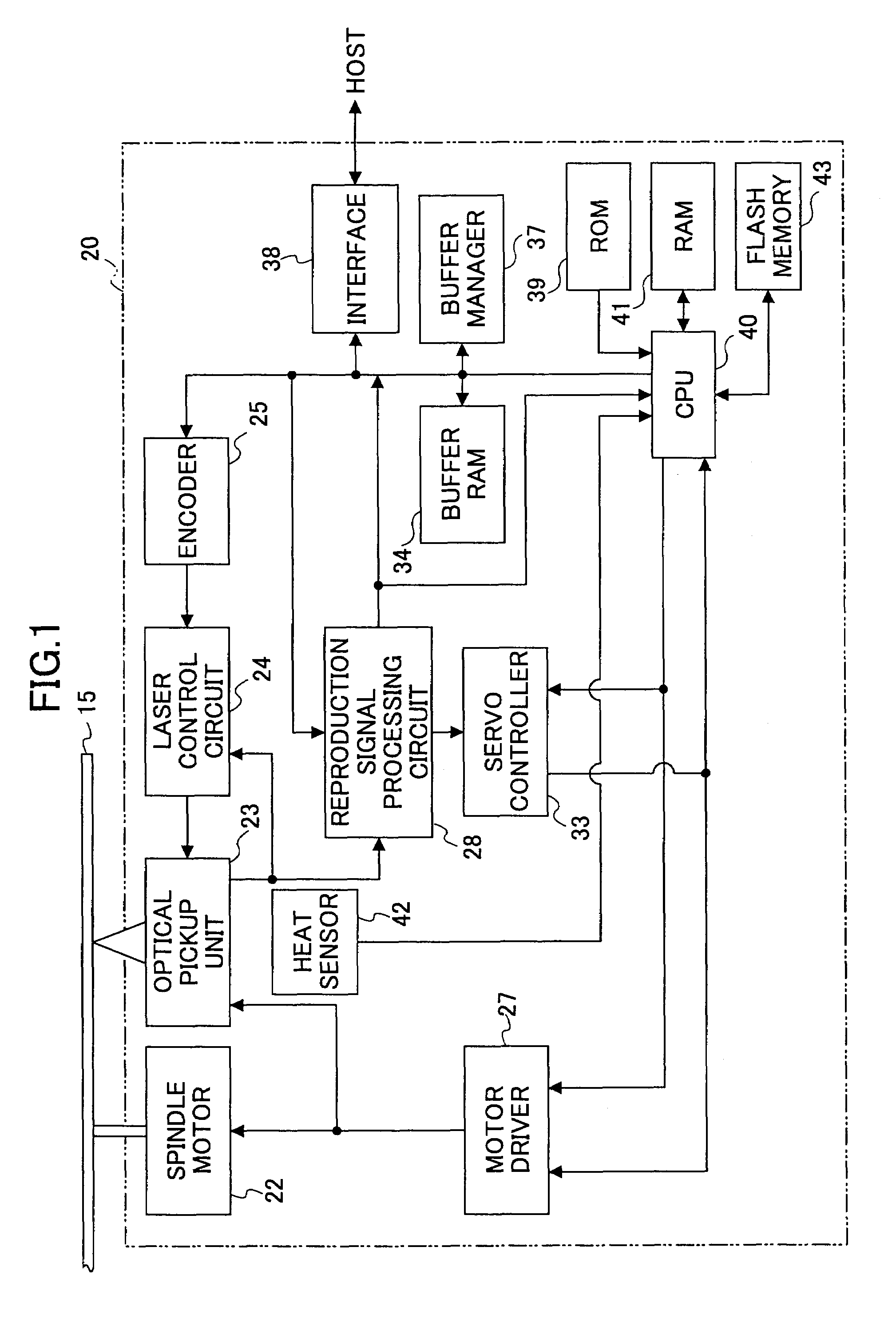
[0073]FIG. 1 is a block diagram showing an optical disk apparatus of the first embodiment of the present invention.

[0074]FIG. 1 shows an optical disk apparatus 20 that includes a spindle motor 22 for rotatatively driving an optical disk 15 serving as an information recording medium, an optical pickup unit 23, a laser control circuit 24, an encoder 25, a motor driver 27, a reproduction signal processing circuit 28, a servo controller 33, a buffer RAM 34, a buffer manager 37, an interface 38, a ROM 39, a CPU 40, a RAM 41, a flash memory 43 serving as a memory unit, and a temperature sensor 42 serving as a temperature detection unit. It is to be noted that the arrows shown in FIG. 1 merely indicate the flow of representative signals and information, and are not to be regarded as indicating all the relations among the blocks illustrated in FIG. 1.

[0075]The optical pickup unit ...

second embodiment

[0139]A second embodiment of the present invention is next described with reference to FIGS. 7 and 8.

[0140]The second embodiment has a feature of employing a method for setting an optimum recording condition which is different from that of the first embodiment. Other components (e.g. optical pickup unit, optical disk apparatus) are the same as the first embodiment. Therefore, mainly the differences between the second embodiment and the first embodiment are hereinafter described. Furthermore, like components of the second and first embodiments are denoted by like numerals and are not further described. Furthermore, the second embodiment is provided under the same conditions as those of the first embodiment.

[0141]ROM 39 has stored a second recording condition setting program instead of the first recording condition setting program.

[0142]A process for setting recording power is next described with reference to FIG. 7. The flow chart in FIG. 7 corresponds to a set of algorithms performe...


PUM


Abstract

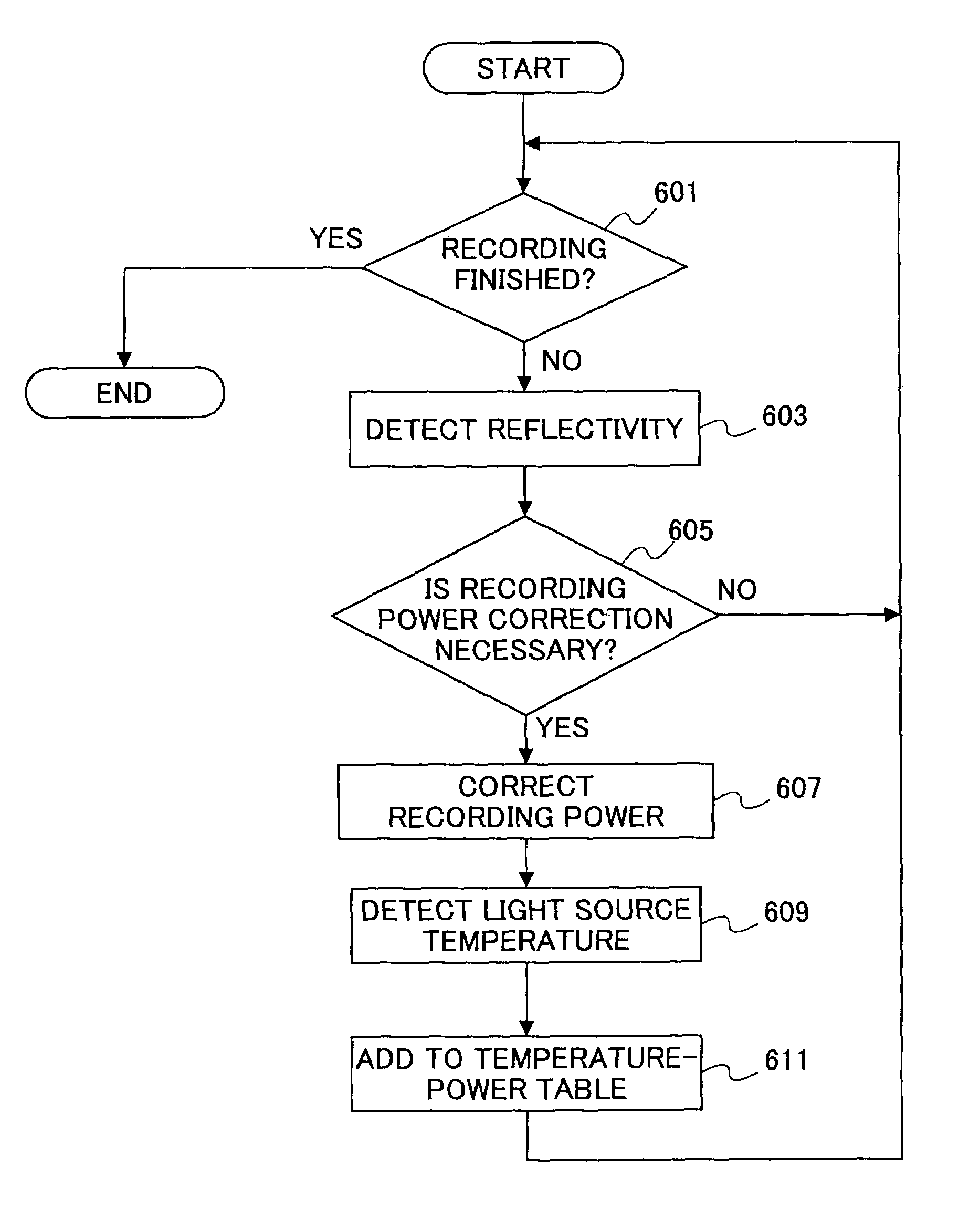
A recording condition setting method includes the steps of: a) obtaining identification information from an information recording medium; b) searching through a table including history information indicative of temperature information detected in the vicinity of a light source and corresponding optimum recording power; c) extracting history information corresponding to the identification information; d) detecting temperature information detected in the vicinity of the light source; e) acquiring an optimum recording power by referring to the temperature information detected in step d) and the history information extracted in step c); and f) setting the optimum recording power acquired in step e) as a recording condition.

Description

BACKGROUND OF THE INVENTION[0001]1. Field of the Invention[0002]The present invention generally relates to a recording condition setting method, program, recording medium, and information recording apparatus. More particularly, the present invention relates to a recording condition setting method for setting a recording condition when recording information to an information recording apparatus, a program used for a recording apparatus, a recording medium having the program recorded thereto, and a recording apparatus for recording information to a recording medium.[0003]2. Description of the Related Art[0004]Due to improvements made in the functions of personal computers in recent years, the personal computer has become able to handle audio-visual information such as music and images. Since audio-visual information contains a vast amount of data, optical disks such as CDs (Compact Disc), and DVDs (Digital Versatile Disc) have gained attention for use as information recording media. F...

Claims


Application Information

Patent Timeline
IPC IPC(8): G11B7/12G11B7/0045G11B7/125G11B7/126
CPCG11B7/126G11B7/00451
Inventor SUZUKI, HARUYUKIYAMAMOTO, NORIHIRO
Owner RICOH KK
Learn More