Gas insulated switchgear

a technology of gas insulated switchgear and switchgear, which is applied in the direction of switchgear arrangements, substations, non-enclosed substations, etc., can solve the problems of difficult to secure a space for monitoring and servicing operations, degraded serviceability/operation, and the effort to downsize gas insulated switchgear, etc., and achieves convenient service/operation. economic

Inactive Publication Date: 2008-02-28
KK TOSHIBA
View PDF1 Cites 10 Cited by
  • Summary
  • Abstract
  • Description
  • Claims
  • Application Information

AI Technical Summary

Benefits of technology

[0014]In view of the above-identified circumstances, it is therefore an object of the present invention to provide a phase isolated type gas insulated switchgear that allows servicing / operating personnel to work without moving far away from the circuit breaker operating mechanism side so that the switchgear can be serviced / operated economically with ease.

Problems solved by technology

As gas insulated switchgears are downsized in pursuit of economy, it becomes difficult to secure a space for monitoring and servicing operations where the operator can access and service the gas insulated switchgear.
The net result is a degraded serviceability / operability.
Differently speaking, the efforts for downsizing gas insulated switchgears confront limitations because a space needs to be secured for servicing operations.
Thus, the need of such a space makes it difficult to realize an economic gas insulated switchgear.
However, the disclosed switchgear is of the three-phase common type and cannot be applied straightly to a switchgear where the disconnectors and the circuit breakers of each phase are separated from those of the other phases by gas compartments.
Additionally, it is not possible to arrange the operating mechanisms in parallel in a horizontal direction with disclosed technique.
Therefore, if the operating mechanisms of a phase isolated type gas insulated switchgear are arranged in a concentrated manner, the height of the operating mechanism side of the switchgear cannot be reduced and hence the efficiency of operation of the switchgear is not improved satisfactorily because the phase isolated type gas insulated switchgear has a height significantly greater than the three-phase common type switchgear (See FIG. 1 of the above-cited Japanese Patent document).

Method used


Image

  • Gas insulated switchgear
  • Gas insulated switchgear
  • Gas insulated switchgear

Examples


first embodiment

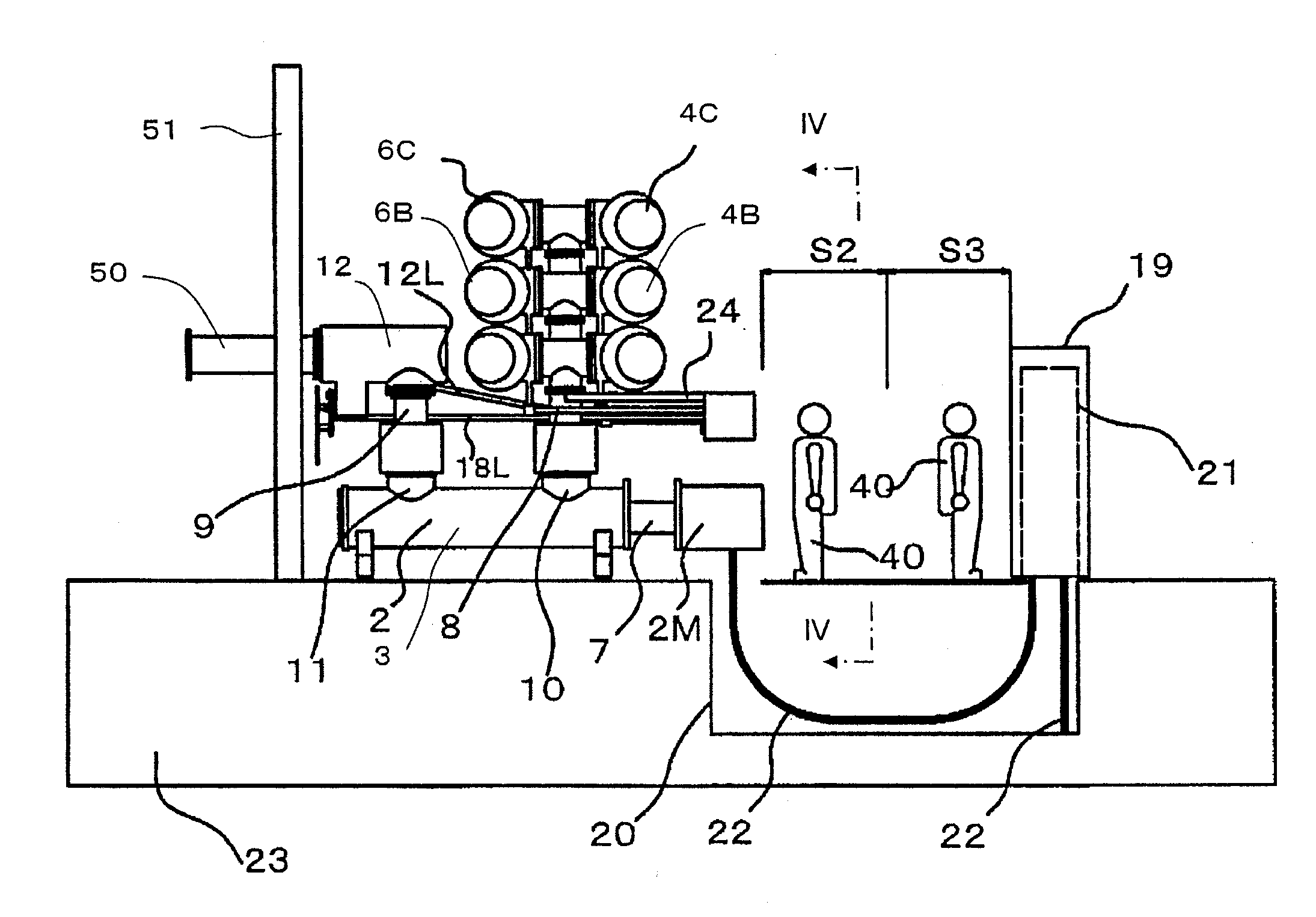
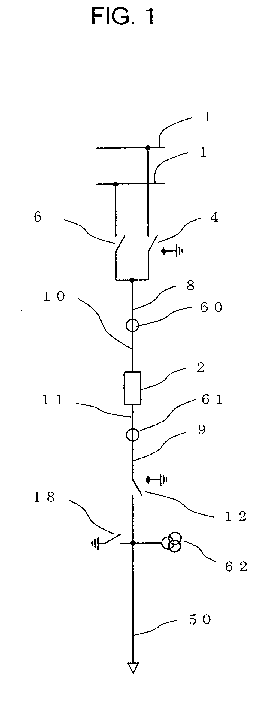
[0040]FIG. 1 is a schematic single line diagram of the first embodiment of gas insulated switchgear according to the present invention. Note that the single line diagram is applicable to all the other embodiments. As shown in FIG. 1, a disconnector and maintenance earthning switch (first disconnector and maintenance earthning switch) 4 for the main bus bars is connected to one of the two main bus bars 1, while a disconnector 6 for the main bus bars is connected to the other main bus bar 1. The disconnector and maintenance earthning switch 4 for the main bus bars and the disconnector 6 for the main bus bars are connected to a first bus bar 8 and then to an end of the circuit breaker 2 by way of first bus bar connecting section 10.

[0041]A second bus bar 9 is connected to the other end of the circuit breaker 2 by way of second bus bar connecting section 11, and a disconnector and maintenance earthning switch (second disconnector and maintenance earthning switch) 12 for the feeder line ...

second embodiment

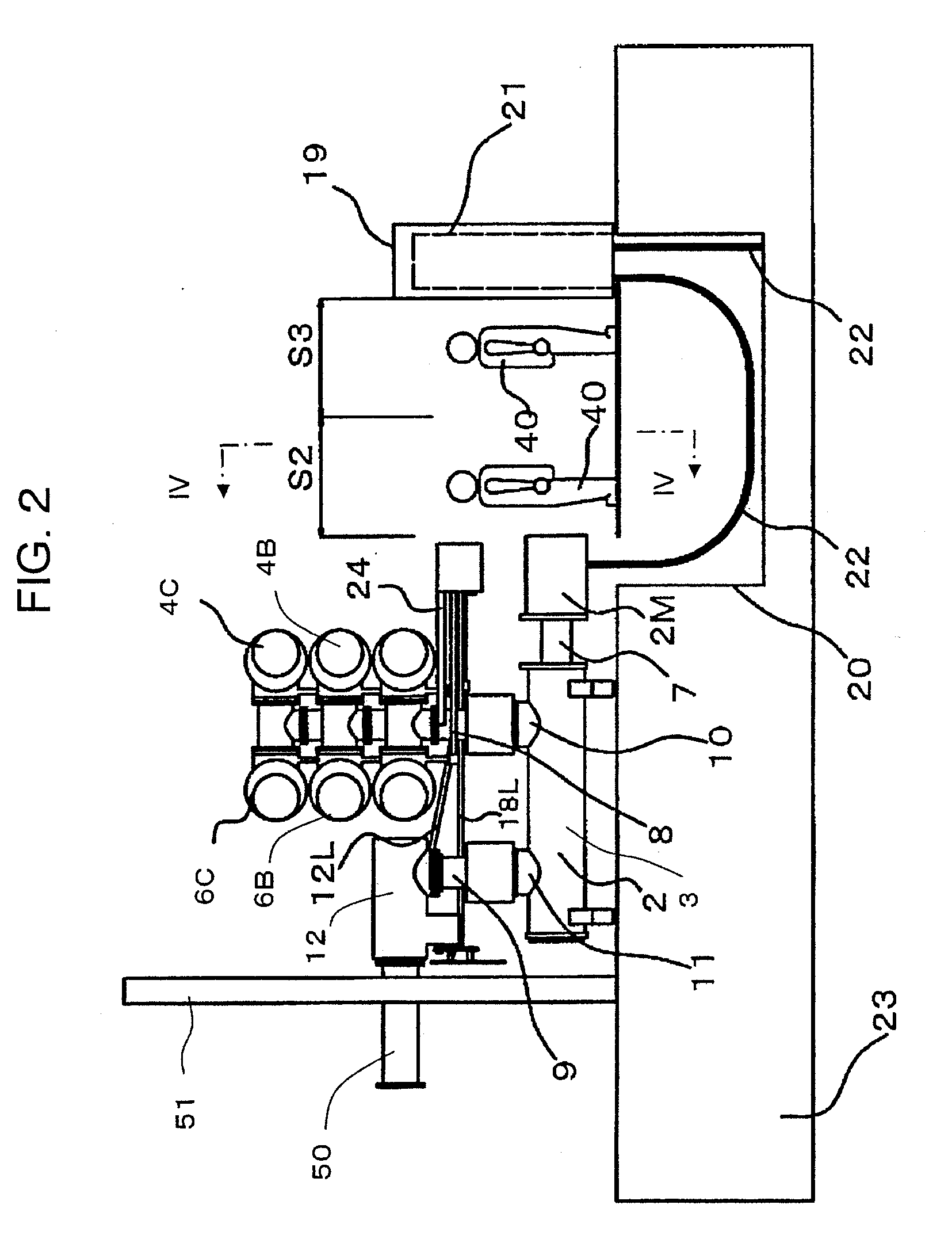
[0060]Now, the second embodiment of gas insulated switchgear according to the present invention will be described below by referring to FIGS. 6 through 14. FIG. 6 is a cross-sectional elevation view of the second embodiment of gas insulated switchgear according to the present invention. FIG. 7 is a plan view of the gas insulated switchgear of FIG. 6. FIG. 8 is a lateral view of the gas insulated switchgear of FIG. 6. FIG. 9 is a perspective view of the gas insulated switchgear of FIG. 6. FIG. 10 is a cross-sectional partial view of the gas insulated switchgear of FIG. 6 as viewed in the direction of the X-X arrow lines in FIG. 6. FIG. 11 is a cross-sectional plan view of the gas insulated switchgear of FIG. 6 as viewed in the direction of the XI-XI arrow lines in FIG. 6. FIG. 12 is a cross-sectional elevation view of the gas insulated switchgear of FIG. 6 as viewed in the direction of the XII-XII arrow lines in FIG. 6. FIG. 13 is a partial lateral view of gas insulated switchgears o...

third embodiment

[0066]Now, the third embodiment of gas insulated switchgear according to the present invention will be described below by referring to FIGS. 15 through 20. FIG. 15 is a cross-sectional elevation view of the third embodiment of gas insulated switchgear according to the present invention. FIG. 16 is a plan view of the gas insulated switchgear of FIG. 15. FIG. 17 is a lateral view of the gas insulated switchgear of FIG. 15. FIG. 18 is an enlarged partial lateral view of the part indicated by XVIII in FIG. 17. FIG. 19 is a schematic perspective view of the operating mechanisms of the third embodiment of gas insulated switchgear, showing the positional arrangement thereof. FIG. 20 is a schematic exploded perspective view of an operating mechanism that can be used for the third embodiment of gas insulated switchgear according to the present invention.

[0067]In this embodiment, the operating mechanisms 4M, 6M, 12M, 18M of all the disconnector and maintenance earthning switches of the feeder...


PUM


Abstract

A gas insulated switchgear has: circuit breakers, circuit breaker vessels, first disconnector and maintenance earthning switches connected to first bus bars connected to circuit breaker vessels and also to main bus bars, second disconnector and maintenance earthning switches connected to second bus bars connected to the circuit breaker vessels, circuit breaker operating mechanisms, first and second disconnector and maintenance earthning switch operating mechanisms, and first and second disconnector and maintenance earthning switch operation links for linking the disconnector and maintenance earthning switches and the operating mechanisms for three phases. The second disconnector and maintenance earthning switch operation links are arranged so as to pass through inter-phases of the first bus bars and the operating panels of the circuit breaker operating mechanism and the first and second disconnector and maintenance earthning switch operating mechanisms of each phase are arranged on a common flat plane.

Description

CROSS-REFERENCE TO RELATED APPLICATIONS[0001]This application is based upon and claims the benefits of priority from the prior Japanese Patent Application No. 2006-191221, filed on Jul. 12, 2006; the entire content of which is incorporated herein by reference.BACKGROUND OF THE INVENTION[0002]1. Field of the Invention[0003]This invention relates to a phase isolated type gas insulated switchgear containing components of each of three phases in separate vessels.[0004]2. Description of the Related Art[0005]Generally, gas insulated switchgears comprise devices containing a charging unit in a hermitically sealed metal vessel along with a highly insulating and arc-extinction insulation medium such as SF6 gas. If compared with air insulated switchgears, gas insulated switchgears can be remarkably downsized and hence can reduce the area of the installation site to a large extent by three-dimensionally arranging the circuit breakers, disconnectors and other required devices in order to reduce...

Claims


Application Information

Patent Timeline
Patent Type & Authority Applications(United States)
IPC IPC(8): H02B13/035H02B1/20H02B13/055H02B5/06
CPCH02B13/0352H02B5/06H02B13/075
Inventor FUKUNAGA, MASAYUKIKOSAKADA, MASAYUKIOKANARI, NOBUAKI
Owner KK TOSHIBA
Why Eureka
Try Eureka