Chucking Device, and Motor and Disc Drive Device Having Loaded Thereon a Chucking Device

a technology of chucking device and chucking disc, which is applied in the direction of magnetic recording, data recording, instruments, etc., can solve the problem of no fitting load of disc, and achieve the effect of preventing clamp error and reducing disc loading for

Active Publication Date: 2008-03-06
NIPPON DENSAN CORP
View PDF12 Cites 22 Cited by
  • Summary
  • Abstract
  • Description
  • Claims
  • Application Information

AI Technical Summary

Benefits of technology

[0011]According to a chucking device of the present invention, when loading a disc to a retainer section, since a guiding section, having an inclined surface so as to guide the disc to the retainer section, is provided axially

Problems solved by technology

As such, when the large disc loading force is required for loading a disc, there may be situations in which the dis

Method used


Image

  • Chucking Device, and Motor and Disc Drive Device Having Loaded Thereon a Chucking Device
  • Chucking Device, and Motor and Disc Drive Device Having Loaded Thereon a Chucking Device
  • Chucking Device, and Motor and Disc Drive Device Having Loaded Thereon a Chucking Device

Examples


Embodiment Construction

Overall Structure of Brushless Motor

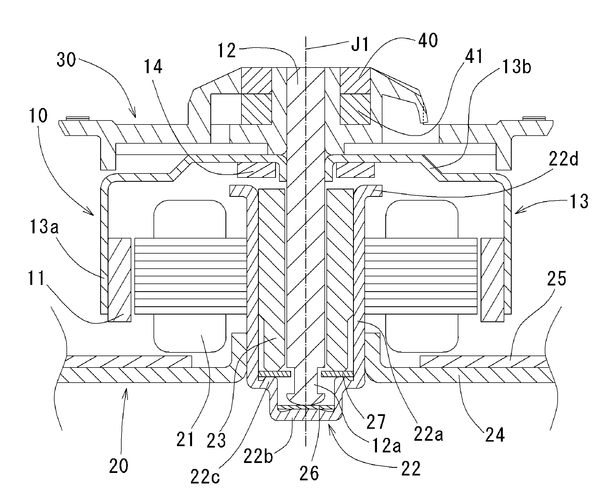
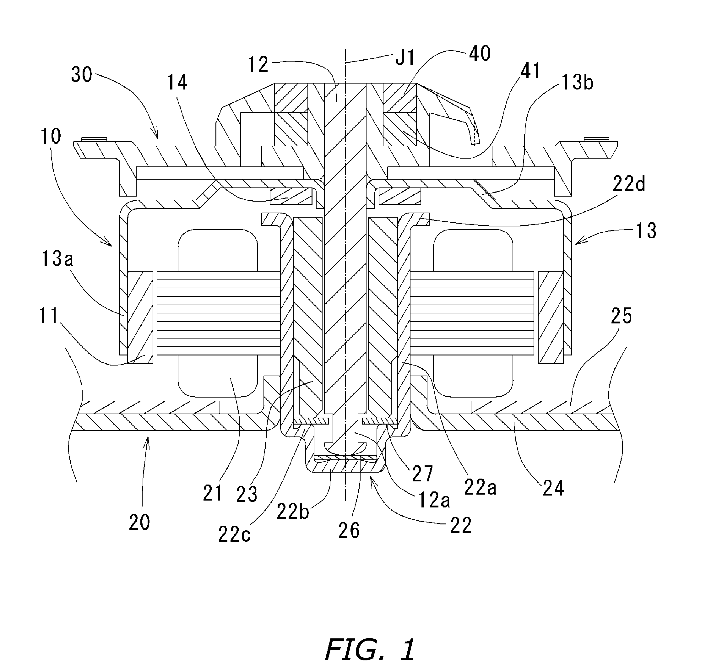
[0028]An entire structure of a brushless motor of the present invention will be described with reference to FIG. 1. FIG. 1 is a diagram illustrating an exemplary cross section, with respect to a rotation axis, of an embodiment of a brushless motor of the present invention.

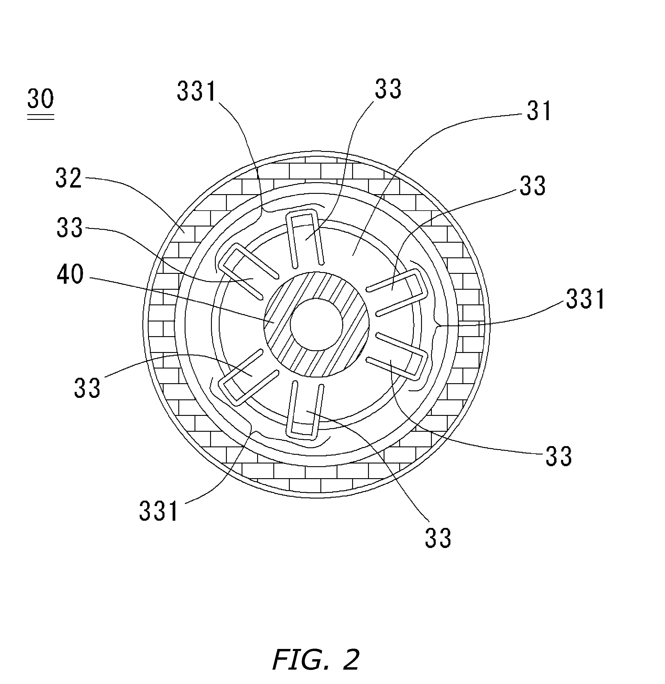
[0029]According to FIG. 1, the brushless motor comprises: a rotor unit 10 including a rotor magnet 11; a stator 21 having a surface parallel to the rotor magnet 11 wherein there is a slight space in a radial direction between the stator and the rotor magnet 11; a stator unit section 20 for supporting the rotor unit 10; and a chucking device 30 for allowing a disc to be attached thereto and removed therefrom.

[0030]First, the rotator 10 will be described.

[0031]The rotator 10 includes: a shaft 12 which is a rotation axis J1; a rotor holder 13 which is a steel sheet pressed into a covered and substantially cylinder shape and is affixed to the shaft 12; a ring shaped rotor magnet 11 a...


PUM


Abstract

A chucking device comprises a retainer section for retaining a disc, a guiding section for guiding the disc to the retainer section, and a supporter for supporting the retainer section and the guiding section. The guiding section has a small enough angle for a guiding section side angle of inclination θ1 so as not to make contact with a upward facing disc, of a multilayer disc, thereby reducing a disc loading force.

Description

BACKGROUND OF THE INVENTION[0001]1. Technical Field[0002]The present invention relates to a chucking device operable to allow a disc, which is for storing and reproducing data, to be attached thereto and removed therefrom, and relates to a motor and to a disc drive device having loaded thereon the chucking device.[0003]2. Description of the Related Art[0004]Conventionally, a chucking device has been developed as means to allow a disc, which is for storing and reproducing data, to be attached thereto and removed therefrom, and to adjust (hereinafter referred to as align) a center of rotation of the disc to a rotation center of a motor. Further, there are expectations in which such chucking device becomes compatible with a high-density multilayer disc such as one illustrated in FIG. 11.[0005]The multilayer disc 1 illustrated in FIG. 11 comprises two discs, 1a and 1b, pasted to one another using an adhesive. The discs 1a and 1b each are provided therein, for example, a 15 mm central op...

Claims


Application Information

Patent Timeline
IPC IPC(8): G11B17/03
CPCG11B33/12G11B25/043
Inventor KANZAWA, RENTAROOE, TAKAYUKIOKAYAMA, YOSHIKI
Owner NIPPON DENSAN CORP
Why Eureka
Try Eureka