Thermal barrier coating system and method of manufacturing the same

a thermal barrier and coating technology, applied in chemical vapor deposition coating, climate sustainability, machine/engine, etc., can solve the problems of cracking and spalling of the ceramic thermal barrier layer, affecting the thermal barrier performance of the ceramic layer, and reducing the strength. , to achieve the effect of improving the thermal barrier performance, suppressing deterioration, and low thermal conductivity

Active Publication Date: 2008-03-27
JAPAN FINE CERAMICS CENT +1
View PDF4 Cites 4 Cited by
  • Summary
  • Abstract
  • Description
  • Claims
  • Application Information

AI Technical Summary

Benefits of technology

[0019] The present invention has been made to solve the above problems of the prior art and an object thereof is to provide a thermal barrier coating system which improves thermal barrier properties and suppresses deterioration due to sintering by imparting low thermal conductivity to a ceramics thermal barrier layer synthesized by an EB-PVD method, and which can exhibit excellent heat resistance and excellent durability for a long period when applied to high-temperature components such as gas turbine parts and jet engine parts, and a method of manufacturing the same.

Problems solved by technology

However, high-temperature components made only of a superalloy of the prior art do not have sufficiently high melting point and are likely to cause softening and decrease in strength due to recrystallization in a high-temperature range, thus causing such fatal restriction that the members cannot be used at a high-temperature of 1000° C. or more.
However, the high-temperature component (heat resisting structural member) formed with a thermal barrier coating layer of the prior art had problems in that it was likely to cause cracking and spalling of the ceramics thermal barrier layer and was inferior in durability and reliability.
Once cracking and spalling occur in the ceramics thermal barrier layer, thermal barrier properties drastically deteriorate, causing rapid temperature rise of the metal substrate.
In the worst case, the metal substrate may be melted or broken.
However, the ceramics thermal barrier layer synthesized by the EB-PVD method had a problem in that it is inferior in thermal barrier effect to the conventional ceramics thermal barrier layer synthesized by the plasma spraying method because of its high thermal conductivity.
In the case of the low thermal barrier effect, the temperature of the metal substrate increases and oxidation is accelerated, and thus spalling of the coating film is likely to occur.
However, the use of a special deposition apparatus and a special technique i's indispensable to control the texture of the ceramics thermal barrier layer so as to provide plural layers in the columnar structure, as disclosed in Patent Document 1, or to form a zig-zag pattern by controlling orientation of the columnar structure, as disclosed in Patent Document 2, and also there was drawbacks such as high equipment cost, high manufacturing cost and high operating cost of the equipment.
Therefore, the above techniques are not suited for practical use.
Even if low thermal conductivity is achieved by the technique, sintering occurs at high temperature and nanopores or gaps, which are effective to achieve low thermal conductivity, disappear, resulting in high thermal conductivity.
As disclosed in Patent Document 3, when the low thermally conductive substance such as Gd2Zr2O7 to be replaced by the stabilized ZrO2 of the prior art is used as the constituent material of the ceramics thermal barrier layer, the low thermally conductive substance is inferior in mechanical properties such as erosion resistance and effective means for overcoming the problem and achieving low thermal conductivity has never been established.
In the case in which the thermal barrier coating system is applied to high-temperature components such as gas turbine parts and jet engine parts, when spalling of the ceramics thermal barrier layer occurs, thermal barrier properties drastically deteriorate, causing rapid temperature rise of the metal substrate, and thus the member is melted or broken, resulting in a serious obstacle during operation of the equipment.
In the case in which an EB-PVD process is applied to a conventional material to form a thermal barrier layer, although the cooling holes are not completely covered, the coating material is deposited around the opening portion, thereby causing problems in that the amount of the cooling gas decreases and satisfactory cooling properties cannot be obtained.

Method used

the structure of the environmentally friendly knitted fabric provided by the present invention; figure 2 Flow chart of the yarn wrapping machine for environmentally friendly knitted fabrics and storage devices; image 3 Is the parameter map of the yarn covering machine
View more

Image

Smart Image Click on the blue labels to locate them in the text.
Viewing Examples
Smart Image
  • Thermal barrier coating system and method of manufacturing the same
  • Thermal barrier coating system and method of manufacturing the same
  • Thermal barrier coating system and method of manufacturing the same

Examples

Experimental program
Comparison scheme
Effect test

example 1

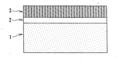
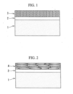
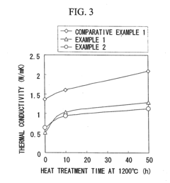
[0061] In Example 1, a thermal barrier coating system having a structure shown in FIG. 1 of Example 1 was manufactured by forming a metal bonding layer 2 (thickness: 100 μm) made of a NiCoCrAlY alloy on the surface of a plate-shaped metal substrate 1 made of a superalloy (HS-188) by a low pressure plasma spraying method, and forming a thermal barrier coating layer 3 (thickness: about 300 μm, porosity: about 25%) having orientation in the (001) direction on the surface of the metal bonding layer 2 by an electron beam physical vapor deposition method (EB-PVD method) using a ZrO2-4 mol % (7 mass %)Y2O3 deposition material containing 5 mol % of La2O3 as a raw material.

example 2

[0062] In Example 2, a thermal barrier coating system of Example 2 was manufactured by forming a metal bonding layer 2 (thickness: 100 μm) made of a NiCoCrAlY alloy on the surface of the same metal substrate 1 as that used in Example 1 by a low pressure plasma spraying method, and forming a thermal barrier coating layer 3 (thickness: about 300 μm, porosity: about 25%) having orientation in the (001) direction on the surface of the metal bonding layer 2 by an EB-PVD method using a (Zr0.75Hf0.25)O2-4 mol % (7 mass %)Y2O3 deposition material containing 5 mol % of La2O3 as a raw material.

example 3

[0063] In Example 3, a thermal barrier coating system of Example 3 was manufactured by forming a metal bonding layer 2 (thickness: 100 μm) made of a NiCoCrAlY alloy on the surface of the same metal substrate 1 as that used in Example 1 by a low pressure plasma spraying method, and forming a thermal barrier coating layer 3 (thickness: about 300 μm, porosity: about 25%) having orientation in the (001) direction on the surface of the metal bonding layer 2 by an EB-PVD method using a (Zr0.5Hf0.5)O2-4 mol % (7 mass %)Y2O3 deposition material containing 5 mol % of La2O3 as a raw material.

the structure of the environmentally friendly knitted fabric provided by the present invention; figure 2 Flow chart of the yarn wrapping machine for environmentally friendly knitted fabrics and storage devices; image 3 Is the parameter map of the yarn covering machine
Login to View More

PUM

PropertyMeasurementUnit
temperatureaaaaaaaaaa
sizeaaaaaaaaaa
volume fractionaaaaaaaaaa
Login to View More

Abstract

A thermal barrier coating system comprising a metal substrate, a metal bonding layer and a ceramics thermal barrier layer wherein the ceramics thermal barrier layer has a columnar structure of a stabilized zirconia containing a stabilizer or a stabilized ZrO2—HfO2 solid solution containing a stabilizer, and comprises 0.1 to 10 mol % of lanthanum oxide.

Description

CROSS REFERENCE TO RELATED APPLICATIONS [0001] The present application is a divisional of U.S. patent application Ser. No. 10 / 779,309, filed Feb. 13, 2004, which claims priority of Japanese Application No. 2003-038867, filed Feb. 17, 2003 and Japanese Application No. 2004-029407, filed Feb. 5, 2004, the entire contents of which is hereby incorporated by reference.BACKGROUND OF THE INVENTION [0002] 1. Field of the Invention [0003] The present invention relates to a low thermally conductive thermal barrier coating system and to a method of manufacturing the same and, more particularly, relates to a low thermally conductive thermal barrier coating system which can effectively reduce the temperature of a metal substrate because its ceramics thermal barrier layer has low thermal conductivity, and which can exhibit excellent heat resistance and excellent durability for a long period when applied to high-temperature components such as gas turbine parts and jet engine parts, and relates to ...

Claims

the structure of the environmentally friendly knitted fabric provided by the present invention; figure 2 Flow chart of the yarn wrapping machine for environmentally friendly knitted fabrics and storage devices; image 3 Is the parameter map of the yarn covering machine
Login to View More

Application Information

Patent Timeline
no application Login to View More
Patent Type & AuthorityApplications(United States)
IPC IPC(8): C08J7/06F01D5/28C23C4/08C23C14/08C23C28/00F01D25/00F02C7/00
CPCC04B35/486C04B2235/3224C04B2235/3225C04B2235/3227C04B2235/3229Y10T428/12611C23C28/3215C23C28/3455Y02T50/67C23C28/321C23C14/08C23C28/00Y02T50/60
InventorMATSUMOTO, MINEAKIYAMAGUCHI, NORIOKIMURA, KAZUSHIGEMATSUBARA, HIDEAKIMATSUNAGA, YASUOMATSUMOTO, KOUICHISHIGEGAKI, YASUHIROARAKI, TAKAHITO
OwnerJAPAN FINE CERAMICS CENT