Cassettte Locking and Ejecting Arrangement

a cassette and locking technology, applied in the field of cassette locking and ejecting arrangement, can solve the problems of tape and/or ink ribbon being correctly aligned, tape and/or ink ribbon being distorted during printing, and the height of the cassette may vary,

Inactive Publication Date: 2008-04-03
DYMO (BVBA)
View PDF9 Cites 114 Cited by
  • Summary
  • Abstract
  • Description
  • Claims
  • Application Information

AI Technical Summary

Benefits of technology

[0014]It is an aim of the present invention to provide an improve

Problems solved by technology

In all the above-described arrangements, a problem exists in that for good quality printing the tape and/or ink ribbon must be correctly aligned with the print head during printing.
However, in such an arrangement, the height of the cassette may vary if the cassette is not fully pushed downwards into the cassette receiving bay.
This can lead to mis-alignment of the tape and print head during printing.
Furthermore, if the cassette

Method used


Image

  • Cassettte Locking and Ejecting Arrangement
  • Cassettte Locking and Ejecting Arrangement
  • Cassettte Locking and Ejecting Arrangement

Examples


Embodiment Construction

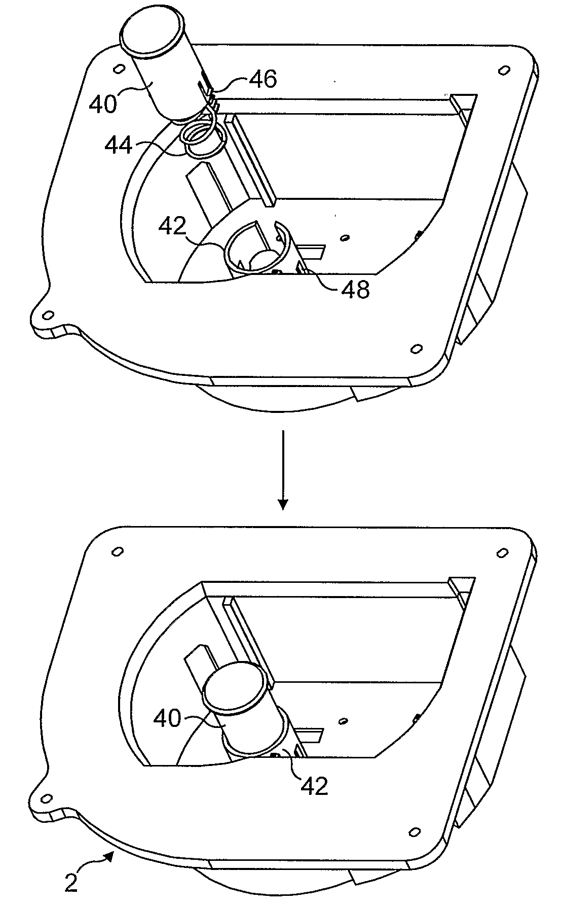
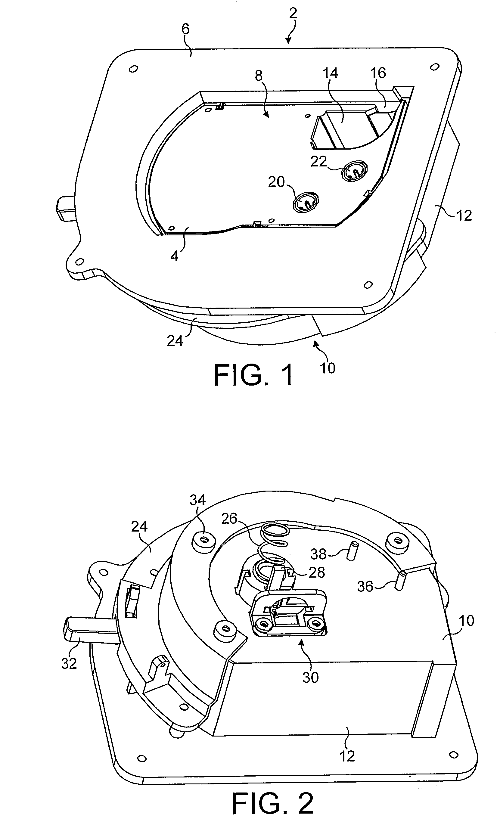
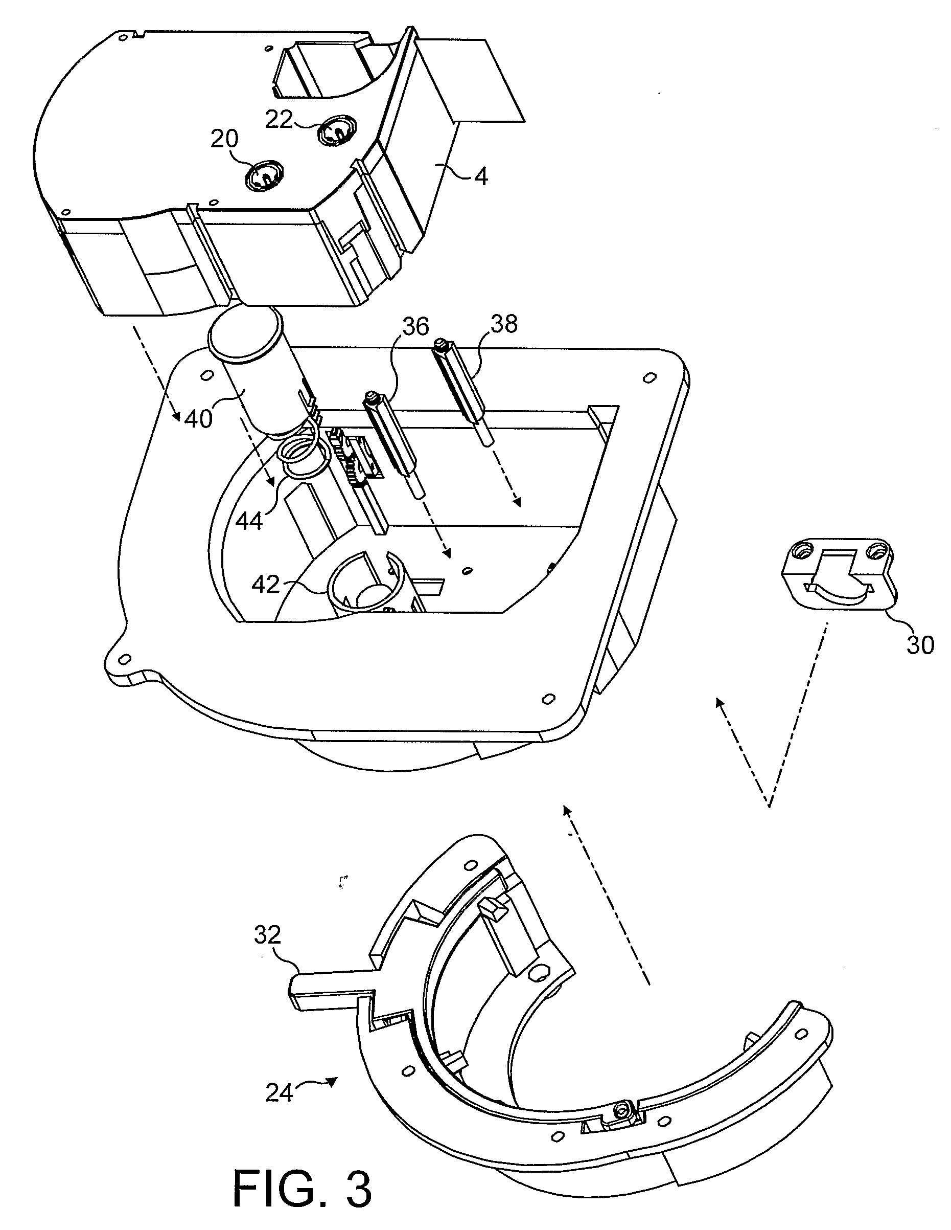
[0051]FIG. 1 shows a top perspective view of a cassette receiving bay 2 with a cassette 4 inserted therein. The cassette receiving bay 2 comprises an upper flange 6 having a recess therein forming an opening 8 for receiving the cassette 4. The cassette receiving bay 2 comprises a base 10 and sides 12 extending from the base 10 to the opening 8. The cassette 4 comprises a housing having a recess 14 therein for receiving a print head and / or platen when the cassette 4 is mounted in a label printer. An opening 16 is provided on a side of the label cassette 4 across which tape passes for co-operation with a print head and a platen in the conventional manner. The illustrated cassette 4 comprises an ink ribbon supply spool 20 and an ink ribbon take up spool 22. A tape supply spool is also housed within the cassette 4. The ink ribbon passes in co-operation with the print receiving tape across the opening for printing. A locking ring 24 is provided for locking the cassette 4 in a printing po...


PUM


Abstract

A label printer comprising a cassette-receiving bay, said cassette-receiving bay having a base, a top opening opposite the base, a locking mechanism, and an ejector mechanism extending from said base, said ejector mechanism having an ejector part having an upper surface for cooperation with a cassette, said ejector part being movable in a first direction towards said base and biased in a second direction towards said top opening such that a force on the ejector part directed towards said base causes the ejector part to move in the first direction and wherein said ejector part is biased to move in said second direction when the force is removed, said ejector mechanism being arranged whereby when a cassette is inserted into the cassette receiving bay, said ejector part extends through an opening in a base of the cassette.

Description

FIELD OF THE INVENTION[0001]The present invention relates to a label printer, and particularly to an arrangement for locking a cassette into a label printer and ejecting it.BACKGROUND OF THE INVENTION[0002]Label printers which uses a supply of tape, housed in a cassette received in the label printer. The tape comprises an image receiving layer and a backing layer which are secured to one another via an adhesive layer. Such label printers include a cutting mechanism for cutting off a portion of the tape after an image has been printed onto the image receiving layer so that the portion of tape having the image can be used as a label. After the tape has been cut, the cut portion of the tape is pulled from the printer through a slit in the printer housing. The backing layer can then be removed allowing the image receiving layer to be secured to an object using the adhesive layer.[0003]The label printer comprises a cassette receiving bay in which a cassette is received for printing. A pr...

Claims


Application Information

Patent Timeline
IPC IPC(8): B41J11/36B41J3/407B41J15/04B41J32/00
CPCB41J3/4075B41J32/00B41J15/044
Inventor VANDERMEULEN, KRIS
Owner DYMO (BVBA)
Why Eureka
Try Eureka