Vehicle side airbag apparatus

a technology for side airbags and vehicles, which is applied in the direction of vehicle components, pedestrian/occupant safety arrangements, vehicle arrangements, etc., can solve the problems of difficult to deploy side airbags of this kind between the head of the occupant and the door window glass

Active Publication Date: 2008-05-01
TOYOTA JIDOSHA KK
View PDF7 Cites 36 Cited by
  • Summary
  • Abstract
  • Description
  • Claims
  • Application Information

AI Technical Summary

Benefits of technology

[0009]The invention provides a vehicle side airbag apparatus that can deploy a head-protection chamber of a side airbag in a substantially vertical direction to between the head of the occupant and the door window glass.

Problems solved by technology

Therefore, it is difficult to deploy a side airbag of this kind to between the head of the occupant and the door window glass.

Method used


Image

  • Vehicle side airbag apparatus
  • Vehicle side airbag apparatus
  • Vehicle side airbag apparatus

Examples


first example embodiment

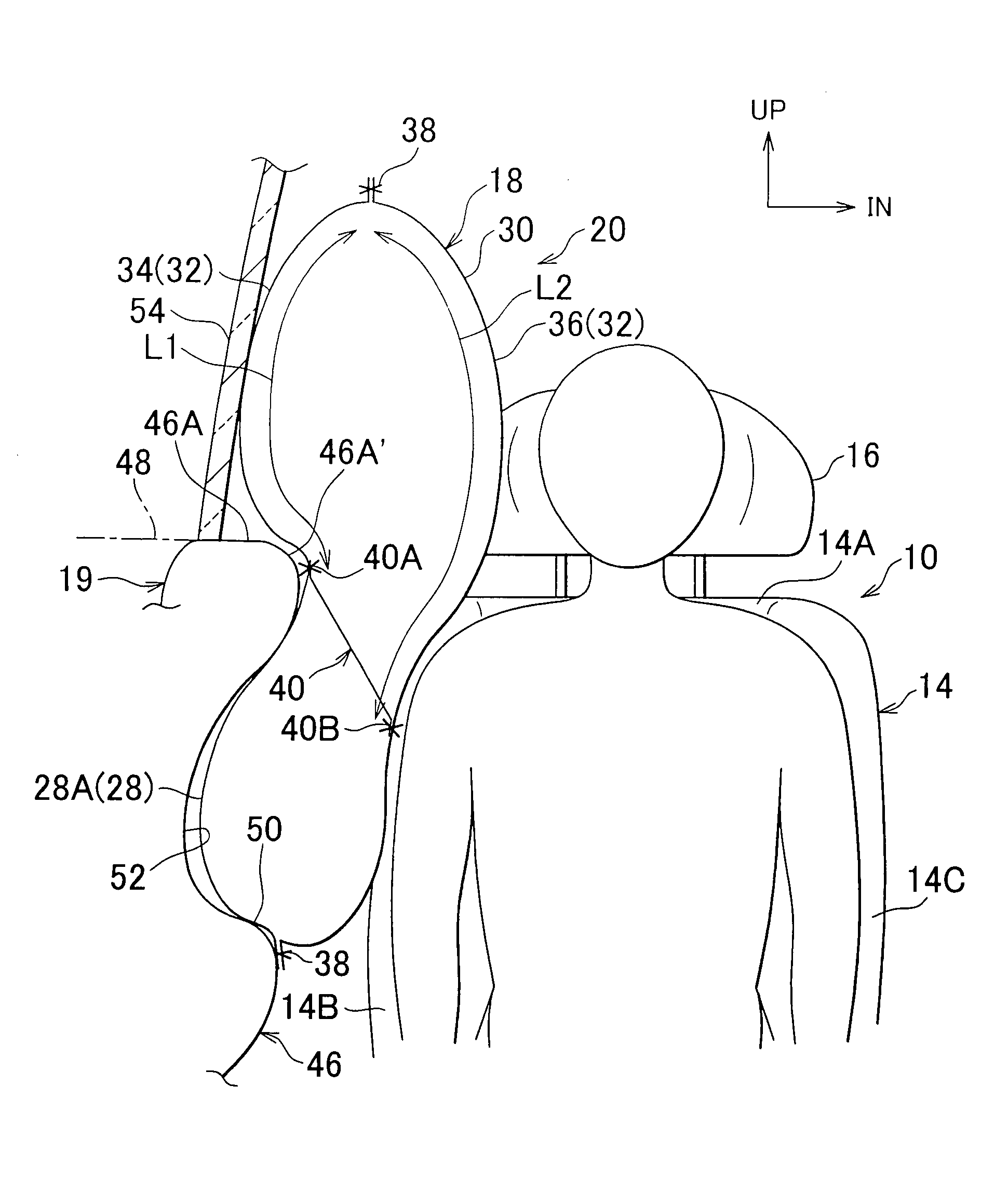
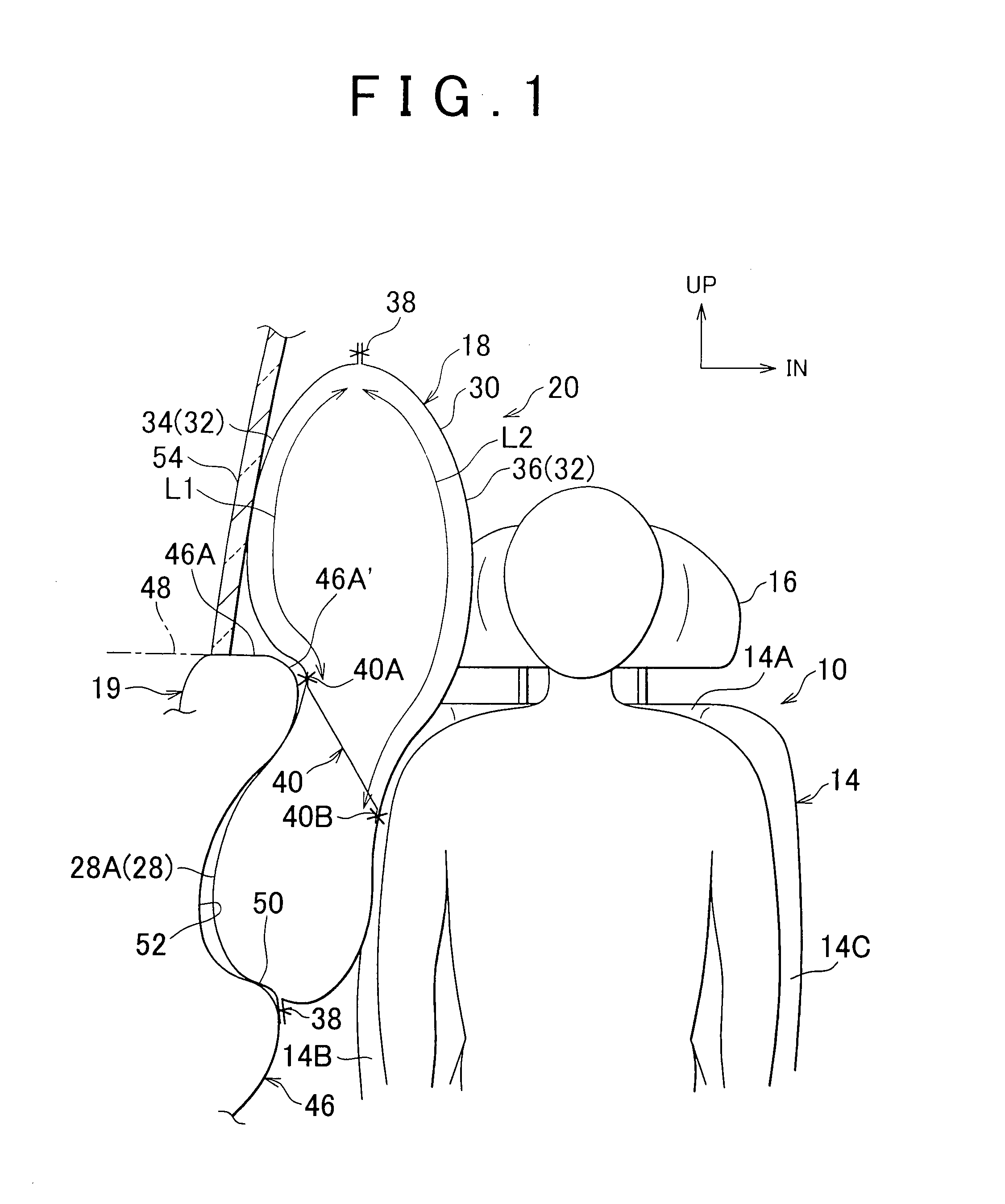
[0021]Hereinafter, a vehicle side airbag apparatus according to the first example embodiment of the invention will be described with reference to FIG. 1 to FIG. 4C. In these drawings, the arrow FR points the front side of the vehicle, the arrow UP points the upper side of the vehicle, and the arrow IN points the inner side of the vehicle in the lateral direction thereof.

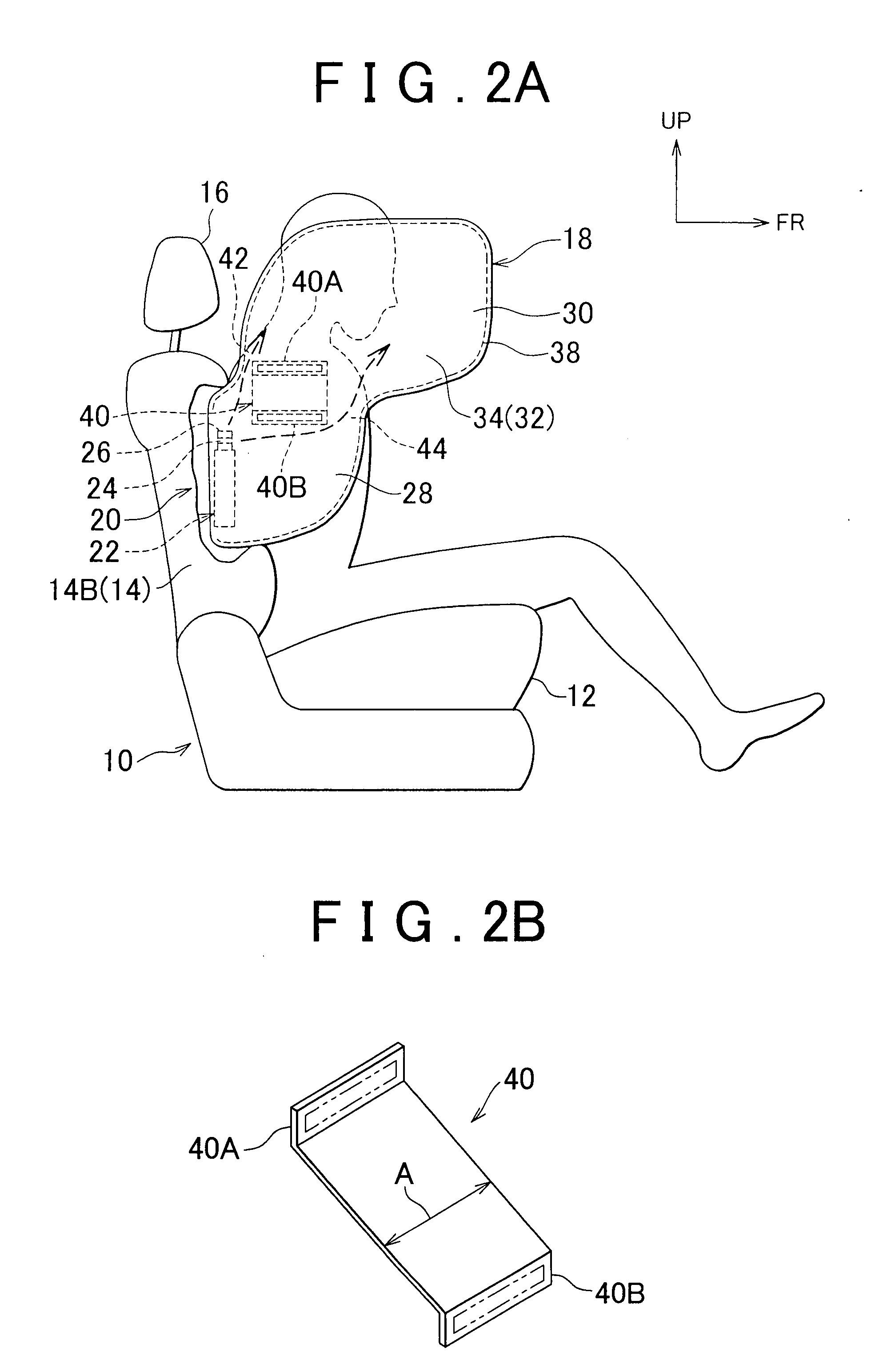
[0022]FIG. 1 is a front view showing a state where the side airbag of the vehicle side airbag apparatus of the first example embodiment is in a deployed state after activation. FIG. 2A is a side view showing the same deployed state of the side airbag of the vehicle side airbag apparatus of the first example embodiment. FIG. 2B is a perspective view showing a strap constituting the main portion of the vehicle side airbag apparatus of the first example embodiment. FIG. 3A and FIG. 3B illustrate a side airbag manufacturing procedure.

[0023]Referring to FIG. 1 and FIG. 2A, a vehicle seat 10 has a seat cushion 12 on which ...

modification examples

of the First Example Embodiment

[0037]Hereinafter, modification examples of the vehicle side airbag apparatus 20 of the first example embodiment will be described with reference to FIG. 5 and FIG. 6. Note that the elements and components that are the same as those in the first example embodiment are denoted by the same reference numerals and their descriptions will be omitted.

[0038](1) In the modification example shown in FIG. 5, the length A′ of a strap 60, which serves as a deployment direction restrictor, in the longitudinal direction of the vehicle is substantially equal to the length B of the boundary between the lower chamber 28 and the upper chamber 30 in the longitudinal direction of the vehicle (Refer to FIG. 3B), and therefore the rear gas passage 42 and the front gas passage 44 described in the first example embodiment are not provided. Alternatively, in this modification example, a circular through hole 62 is formed at the center of the strap 60, which serves as a gas pas...


PUM


Abstract

Aside airbag has a lower chamber corresponding to the chest of the occupant and an upper chamber corresponding to the head of the occupant. A strap is provided at the boundary between the lower and upper chambers. The attachment position of a door-side attachment portion of the strap is higher than the attachment position of a seat-side attachment portion of the strap and lower than the upper end of a door trim or at the same height as the upper end of the door trim. Thus, the peripheral length from the upper end of a door-side base cloth of the side airbag to the door-side attachment portion of the strap is shorter than the peripheral length from the upper end of a seat-side base cloth of the side airbag to the seat-side attachment portion of the strap. As such, upon deployment of the side airbag, the upper chamber can be raised up toward a door window glass.

Description

INCORPORATION BY REFERENCE[0001]The disclosure of Japanese Patent Application No. 2006-294511 filed on Oct. 30, 2006 including the specification, drawings and abstract is incorporated herein by reference in its entirety.BACKGROUND OF THE INVENTION[0002]1. Field of the Invention[0003]The invention relates to a vehicle side airbag apparatus for protecting the head and chest of an occupant.[0004]2. Description of the Related Art[0005]In recent years, side airbags have been proposed which are long in the vertical direction and large in size to realize an extended occupant protection area that also covers the head of the occupant as well as the chest (Refer to Japanese Patent No. 3467473).[0006]Japanese Patent No. 3467473 describes a side airbag that is manufactured by sewing a vehicle-outer-side base cloth and a vehicle-inner-side base cloth together into the shape of a bag. In this side airbag, a tether (partitioning cloth) in which a plurality of communication holes are formed is sewn...

Claims


Application Information

Patent Timeline
Patent Type & Authority Applications(United States)
IPC IPC(8): B60R21/21B60N2/42B60N2/427B60R21/20B60R21/207B60R21/2338
CPCB60R21/23138B60R21/233B60R2021/23382B60R21/2346B60R21/2338
Inventor FUKAWATASE, OSAMUSEKIZUKA, MAKOTOITO, YASUSHI
Owner TOYOTA JIDOSHA KK
Why Eureka
Try Eureka