Radar device

a technology of a radar and a distance sensor, which is applied in the direction of measurement devices, communication jamming, instruments, etc., can solve the problems of reducing the period of time during which the distance to the target and the relative velocity of the target can be measured, the control of the vehicle, and the inefficiency of the measuremen

Inactive Publication Date: 2008-05-01
MITSUBISHI ELECTRIC CORP
View PDF4 Cites 14 Cited by
  • Summary
  • Abstract
  • Description
  • Claims
  • Application Information

AI Technical Summary

Benefits of technology

[0012]The present invention has been made to solve the above-mentioned problems, and an object of the present invention is to provide a radar device which is cable of detecting an interference signal from the frequency analysis results which are obtained by a difference between a transmitter signal and a receiver signal in all beam directions without stopping the transmission of electromagnetic waves.
[0014]According to the present invention, it is possible to detect the interference signal from the frequency analysis results which are obtained by the difference between the transmitter signal and the receiver signal in all beam directions without stopping the transmission of electromagnetic waves. Accordingly, since the interference signal that is caused by the electromagnetic waves which are transmitted from another on-vehicle radar or a communication device can always be monitored, it is possible to detect the interference signal at a high speed.

Problems solved by technology

In this situation, although there exists the target, it is impossible to measure the distance to the target and the relative velocity of the target, which causes a problem in controlling the vehicle.
However, in the radar device which is disclosed in JP 2004-163340 A, because the transmission of the electromagnetic waves stops during the interference detecting operation, the measurement of the distance to the target and the relative velocity of the target must be suspended, which is not efficient.
Also, when the interference detecting operation is conducted with high frequency in order to enhance the sensitivity of the interference detection, there arises such a problem that a period of time during which the distance to the target and the relative velocity of the target can be measured is reduced.
However, because there is no distinction between a case where the signal intensity increases due to the receiver signal that is reflected by the target and a case where the signal intensity increases due to the interference signal, the above-mentioned method is not suitable for detecting the interference signal.

Method used


Image

  • Radar device
  • Radar device
  • Radar device

Examples


first embodiment

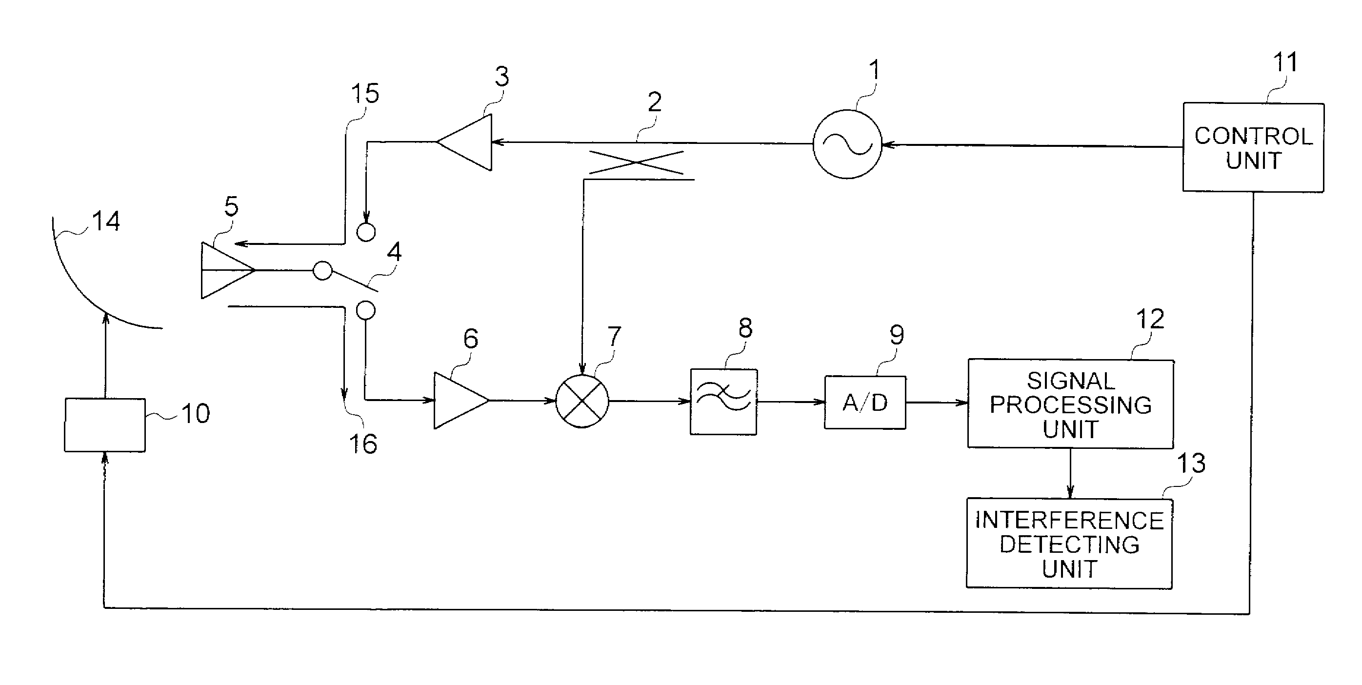
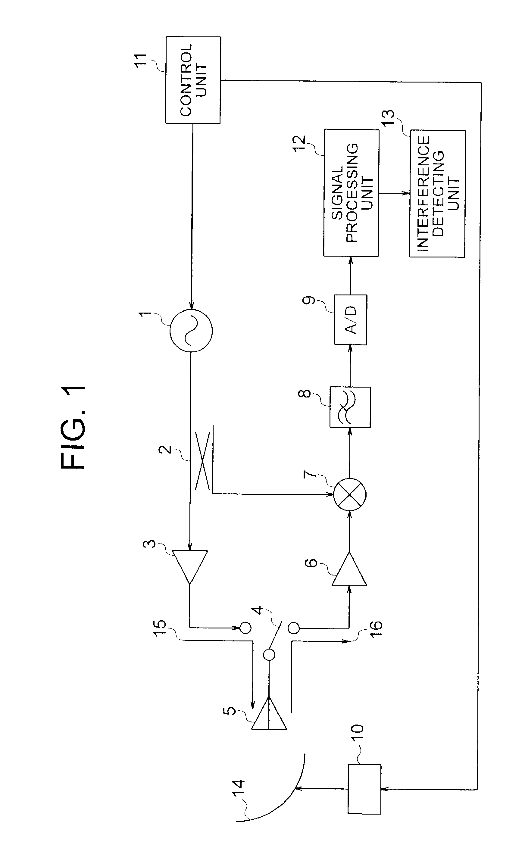
[0025]FIG. 1 is a block diagram showing a configuration of a radar device according to a first embodiment of the present invention. The radar device shown in FIG. 1 represents a radar device of an FM - pulse Doppler system, and includes, as a transmitter circuit, a voltage control oscillator 1 for generating a signal according to an applied voltage waveform, a directive coupler 2 for supplying the signal that is outputted from the voltage control oscillator 1 to a transceiver circuit, an amplifier 3 for amplifying an output signal of the directive coupler 2, a transmission / reception changeover switch 4 for changing over the transmission / reception of the radar, and a transmission / reception antenna 5 for both of transmission and reception.

[0026]Also, the radar device shown in FIG. 1 includes, as a receiver circuit, a low-noise amplifier 6 for amplifying a receiver signal, a mixer 7 for mixing a receiver signal which is an output signal of the low-noise amplifier 6 with a transmitter s...

second embodiment

[0048]A second embodiment is identical in the configuration with the first embodiment except that the interference detecting unit 13 monitors whether the signal intensity in the frequency range that is not used for measurement of the distance to the target and the relative velocity of the target exceeds the threshold value or not, in the plurality of range gates that are equal to or more than a given rate, and it is determined that the interference occurs in the case where the signal intensity exceeds the threshold value in the monitored range gates.

[0049]According to the second embodiment, since it is determined whether the interference occurs or not, by using not all of the range gates, but the plurality of range gates of the given rate or more, it is possible to determine that the interference occurs with a high precision and at a higher speed than that of the first embodiment.

third embodiment

[0050]A third embodiment is identical in the configuration with the first embodiment except that the interference detecting unit 13 monitors whether the signal intensity in the frequency range that is not used for measurement of the distance to the target and the relative velocity of the target exceeds the threshold value Ith or not, in a given range gate, and it is determined that the interference occurs in the case where the signal intensity exceeds the threshold value in the monitored range gate.

[0051]In the case where the longest distance range gate is used as the given range gate, the maximum frequency fb_max(n) (Hz) of the beat signal which is used for measurement of the distance to the target and the relative velocity of the target is the largest. Therefore, because the frequency range that is not used for measurement of the distance to the target and the relative velocity of the target is narrow, that is, a range in which the interference is monitored is narrow, the amount o...


PUM


Abstract

A radar device is mounted on a vehicle, for detecting an object, and includes: a transmitting unit for transmitting an electromagnetic wave as a transmitter signal; a receiving unit for receiving a reflected signal that is reflected from the object as a receiver signal; a signal processing unit for measuring a distance and a relative velocity between the vehicle and the object on the basis of a beat signal that is obtained by the transmitter signal and the receiver signal; and an interference detecting unit for detecting the interference signal from another radar device or a communication device on the basis of a signal intensity of the frequency range that is not used for measuring the distance to the object and the relative velocity of the object.

Description

BACKGROUND OF THE INVENTION[0001]1. Field of the Invention[0002]The present invention relates to a radar device that is mounted on a vehicle for detecting an object (target) such as a preceding vehicle that exists around an own vehicle and measuring a distance thereof from the own vehicle and a relative velocity of the object with respect to the own vehicle.[0003]2. Description of the Related Art[0004]A radar device installed on an own vehicle transmits an electromagnetic wave as a transmitter signal, receives a reflected signal that is reflected by a target such as a preceding vehicle as a receiver signal, and calculates a distance and a relative velocity between the own vehicle and the target on the basis of a frequency analysis result with respect to a difference between the transmitter signal and the receiver signal. The radar device is used in an obstacle proximity warning system, an inter-vehicle distance control system, or a traffic jam following system.[0005]In the radar dev...

Claims


Application Information

Patent Timeline
Patent Type & Authority Applications(United States)
IPC IPC(8): G01S13/00G01S13/931
CPCG01S7/023G01S13/931G01S13/26G01S13/18
Inventor AKITA, KENICHINAKAGAWA, KADO
Owner MITSUBISHI ELECTRIC CORP
Why Eureka
Try Eureka