Apparatus and method for detecting contact position of robot

A contact position and robot technology, applied in the field of contact position devices, can solve the problems of low operation efficiency and large delay in contact position detection, and achieve the effect of efficient detection

Inactive Publication Date: 2011-11-09
YASKAWA DENKI KK
View PDF10 Cites 15 Cited by
  • Summary
  • Abstract
  • Description
  • Claims
  • Application Information

AI Technical Summary

Problems solved by technology

[0004] However, in the conventional contact position detection method using the contact sensing method, the contact part of the robot that contacts the work object is a rigid body, so the speed at the time of contact needs to be suppressed.
Therefore, the more contact points the robot has with respect to the work object, the greater the delay in the detection of the contact position, and the lower the work efficiency

Method used


Image

  • Apparatus and method for detecting contact position of robot
  • Apparatus and method for detecting contact position of robot
  • Apparatus and method for detecting contact position of robot

Examples


Embodiment Construction

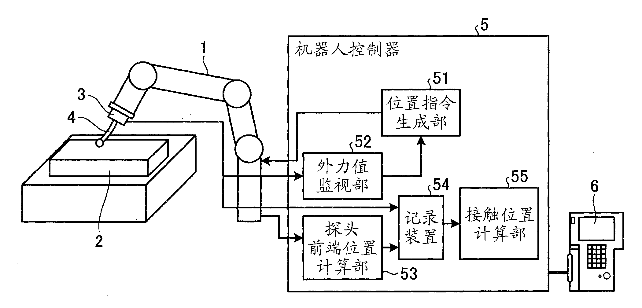
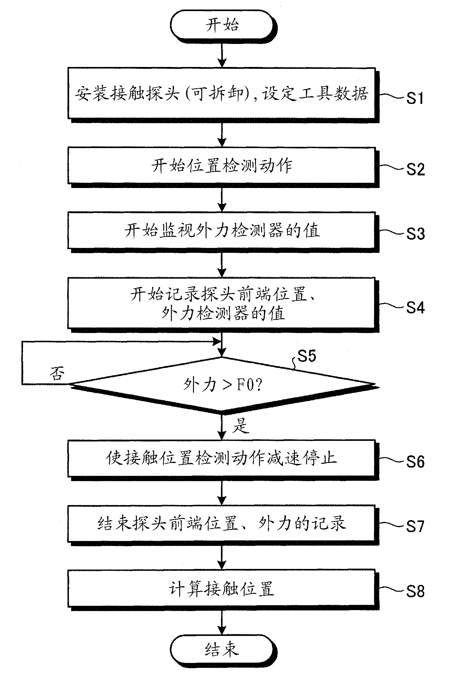
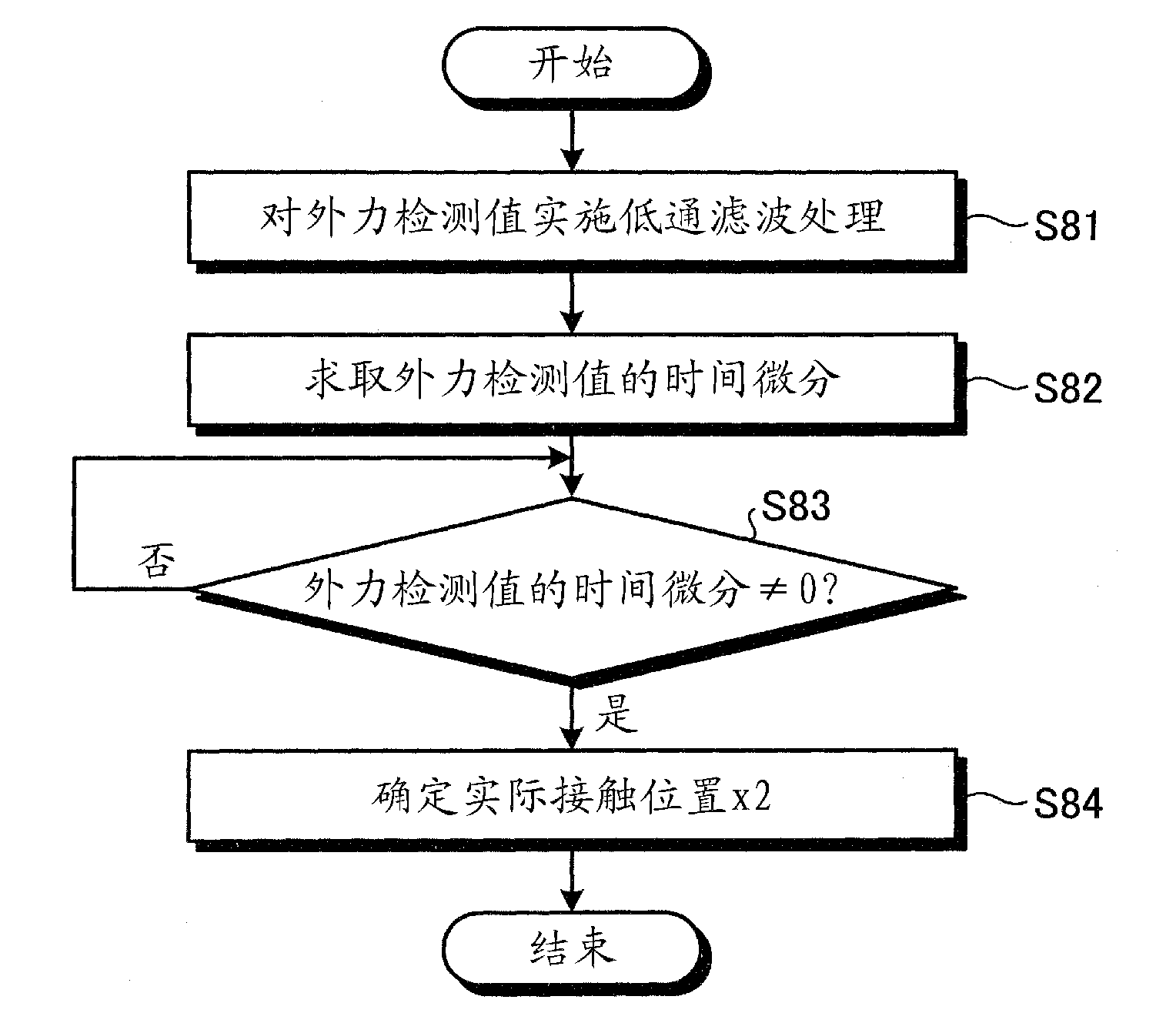
[0025] A device according to an embodiment is a device for detecting a contact position where a robot contacts an object, and includes a probe, a probe position calculation unit, a contact detection unit, and a contact position calculation unit. A probe is mounted on the robot capable of elastic displacement in the direction of contact with the object. The probe position calculation unit calculates the position of the probe with respect to the robot in operation. The contact detection unit detects a state in which the probe is in contact with an object. When the contact state of the probe is detected, the contact position calculation unit derives the contact position from the calculated position of the probe. Preferably, the device further includes a deceleration stop unit that decelerates and stops the robot when the contact state of the probe is detected.

[0026] The probe of the embodiment may have any structure as long as it can elastically displace in the direction in ...


PUM


Abstract

An apparatus for detecting a contact position where a robot makes contact with an object includes a probe, a probe-position calculating unit, a contact detecting unit, and a contact-position calculating unit. The probe is attached to the robot and is configured to make a displacement in a direction of making contact with the object in an elastic manner. The probe-position calculating unit calculates a position of the probe of the robot in operation. The contact detecting unit detects a contact state of the probe with the object. When the contact state of the probe is detected, the contact-position calculating unit derives the contact position based on a calculated position of the probe.

Description

technical field [0001] The disclosed embodiments relate to apparatus and methods for detecting contact locations of a robot. Background technique [0002] In the case of causing the robot to perform work, between the position of the work object (or a defined coordinate system) taught in advance as the work program and the actual position of the work object (or a defined coordinate system), Sometimes errors exist. Therefore, when the position of the work object is predetermined before the start of work and there is an error, it is necessary to perform processing to correct the error. Non-contact sensing means such as laser light and images are generally used as means for detecting the position of work objects. However, in the non-contact sensing method, a step of receiving and processing reflected light from an object is used, and therefore, there is a general technical problem that accurate position detection cannot be performed according to the surface material of the obj...

Claims


Application Information

Patent Timeline
Patent Type & Authority Applications(China)
IPC IPC(8): B25J19/00B25J13/00
CPCG05B19/401
Inventor 神谷阳介井上康之永田英夫
Owner YASKAWA DENKI KK
Why Eureka
Try Eureka