Engine mount bearing sleeve repair

a technology for engine mounts and bearing sleeves, which is applied in bearing repair/replacement, bearing rigid support, manufacturing tools, etc., can solve problems such as wear and damage to link assemblies, and achieve the effect of retaining and preventing relative movemen

Active Publication Date: 2008-05-08
RTX CORP
View PDF7 Cites 10 Cited by
  • Summary
  • Abstract
  • Description
  • Claims
  • Application Information

AI Technical Summary

Benefits of technology

[0008]A sizing sleeve is selected to be of a diameter, such that it will be press fit into the inner surface of the bearing bore. The sizing sleeve has an inner bore that receives an outer surface of a new bearing as a press fit. The bearing is press fit into the sizing sleeve and sizing sleeve is press fit into the bearing bore. When pressed together there are gaps between the link chamfers and the sizing sleeve and the bearing. An outer surface of the sizing sleeve and the bearing is swaged into the link chamfers to retain the components in the link. Swaging the bearing and the sizing sleeve assists in retaining and preventing relative movement between the bearing, sizing sleeve and link arm. The link arm is then reassembled with the link assembly and the engine mount. This same basic repair method can be applied to other engine mount bearings.

Problems solved by technology

Over time the bearings move relative to the link assembly causing wear and damage to the link assemblies.

Method used


Image

  • Engine mount bearing sleeve repair
  • Engine mount bearing sleeve repair
  • Engine mount bearing sleeve repair

Examples


Embodiment Construction

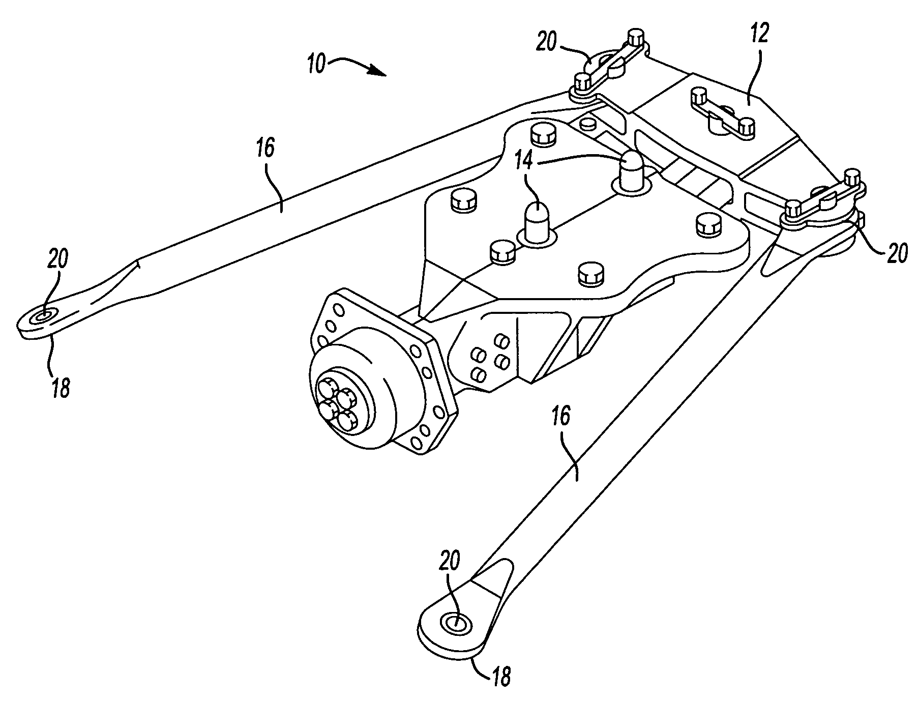
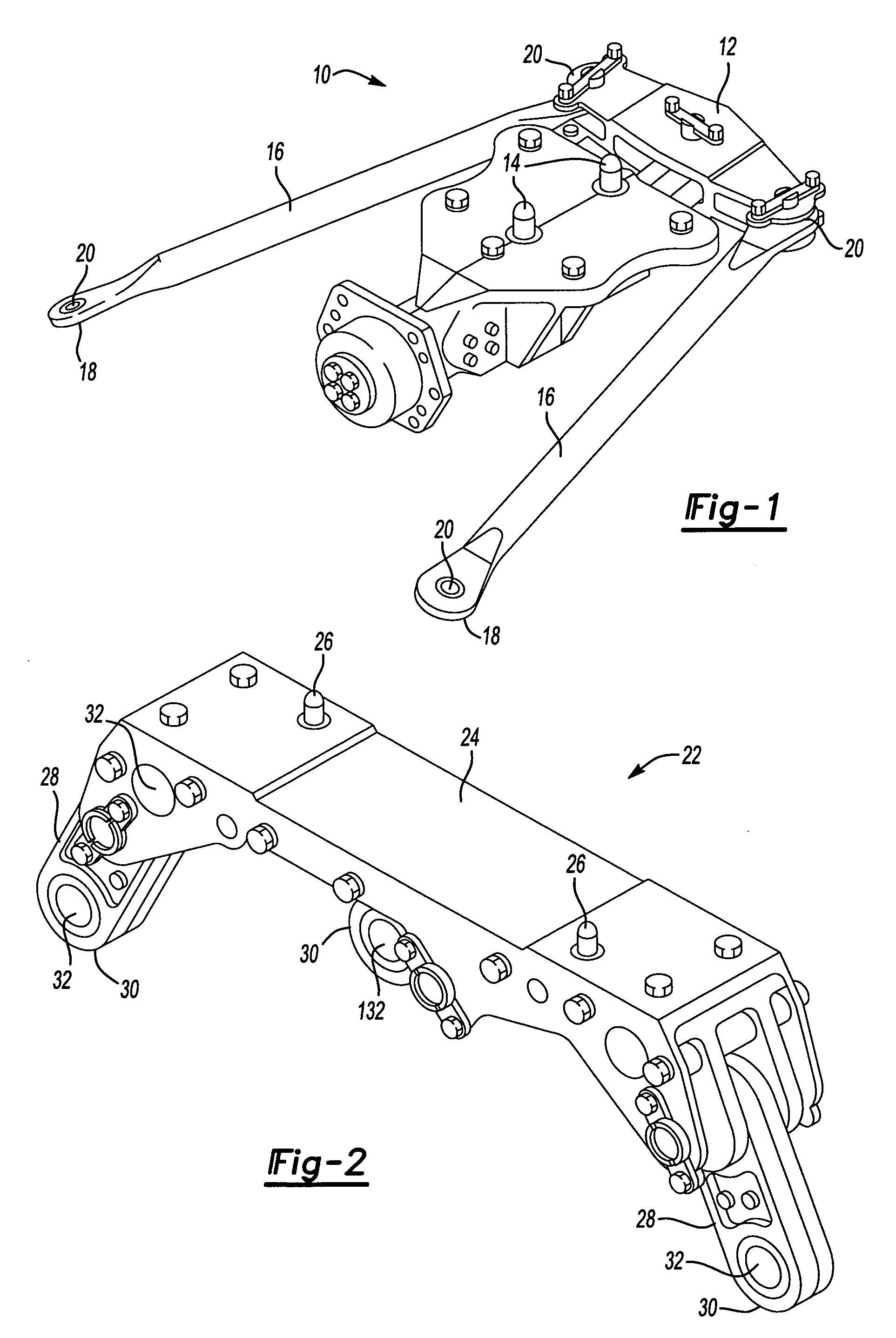
[0017]FIG. 1 is a perspective view of an example forward engine mount 10 for an aircraft. The forward engine mount 10 supports the engine on the wing and assists in transferring thrust of the engine to the aircraft. The forward engine mount 10 includes a beam assembly 12 having wing mounting points 14 to connect the forward engine mount 10 to a wing of the aircraft. Link assemblies 16 extend outward from the beam assembly 12. The link assemblies 16 each have engine mounting points 18 to connect the engine to the forward engine mount 10. Each of the link assemblies 16 has a bearing 20 at the attachment of the link assembly 16 to the beam assembly 12. Additionally, bearings 20 may also be located at the engine mounting points 18.

[0018]FIG. 2 is a perspective view of an example aft engine mount 22 for an aircraft. The aft engine mount 22 supports the engine on the aircraft housing, specifically the turbine exhaust case, and assists in absorbing vertical movement as a result of the weig...


PUM

PropertyMeasurementUnit
diameteraaaaaaaaaa
outer diameteraaaaaaaaaa
inner diameteraaaaaaaaaa

Abstract

Bearing bores for engine mount components must be periodically repaired. A component is disassembled and a bearing is removed from the bearing bore. An inner surface of the bearing bore is machined to remove any damage. A sizing sleeve is selected to have a press fit with the machined inner surface of the bearing bore and with the outer surface of a new bearing. The bearing is press fit into the sizing sleeve and the sizing sleeve is press fit into the bearing bore. The outer surfaces of the sizing sleeve and the bearing are swaged to assist in retaining and preventing relative movement between the bearing, sizing sleeve and engine mount component.

Description

BACKGROUND OF THE INVENTION[0001]The present invention relates generally to a method of repairing an aircraft engine mount and more particularly, to a method of repairing a bearing bore formed in an aircraft engine mount by utilizing a sleeve.[0002]Aircraft utilize engine mounts to retain an engine. Typically, multiple engine mounts are associated with each engine. Several bearings are present in each engine mount, with the bearing pressed into a bearing bore. Forward and aft engine mounts are located between a wing of the aircraft and the engine. The bearings assist in transferring engine thrust to the wing. Aft engine mounts are located between the aircraft housing and the engine and the bearings in those engine mounts assist in transferring vertical movement of the engine to the wing.[0003]Over time the bearings may shift within the bearing bore causing wear or damage to the bearing bore. At periodic intervals over the life of the aircraft the engine mounts are removed and the be...

Claims


Application Information

Patent Timeline
Patent Type & Authority Applications(United States)
IPC IPC(8): B23P6/00
CPCB23P6/00Y10T29/49652B64D2027/268B64F5/0081F16C23/04F16C35/02Y10T29/49938Y10T29/4973Y10T29/49726Y10T29/4994Y10T29/49638Y10T29/49233Y10T29/49011Y10T29/49718B64D2027/266B64F5/40F16C2237/00F16C2326/43
Inventor GRATTON, ANDREW R.
Owner RTX CORP
Why Eureka
Try Eureka