Device and method for less invasive surgical stabilization of pelvic fractures

a technology of pelvic fracture and surgical stabilization, which is applied in the field of implantable plates and/or rod systems, can solve the problems of blockade of subsequent abdominal surgery, high risk of pin tract infections, and complex fracture types

Active Publication Date: 2008-05-08
PARSELL DOUGLAS ERIC +1
View PDF71 Cites 38 Cited by
  • Summary
  • Abstract
  • Description
  • Claims
  • Application Information

AI Technical Summary

Benefits of technology

The patent describes a way to stabilize pelvic fractures using a special hardware system and attachment devices that are positioned between the skin and muscle or along the pelvic bone surface. This method helps to keep the fracture in place and can provide a safer and effective treatment for these types of injuries.

Problems solved by technology

The patent text discusses the current methods used to treat pelvic fractures, which can be either internal or external fixation. The technical problem addressed in the patent is to provide a surgical hardware system that allows for submuscular or supramuscular/subcutaneous internal fixation of anterior pelvic instability through a minimally invasive surgical approach.

Method used


Image

  • Device and method for less invasive surgical stabilization of pelvic fractures
  • Device and method for less invasive surgical stabilization of pelvic fractures
  • Device and method for less invasive surgical stabilization of pelvic fractures

Examples


Embodiment Construction

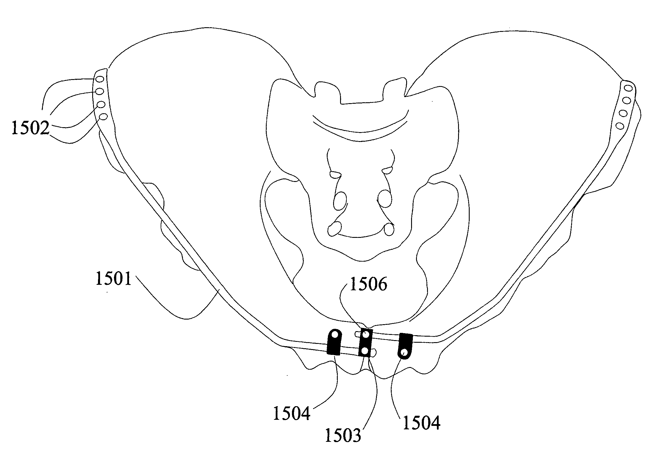
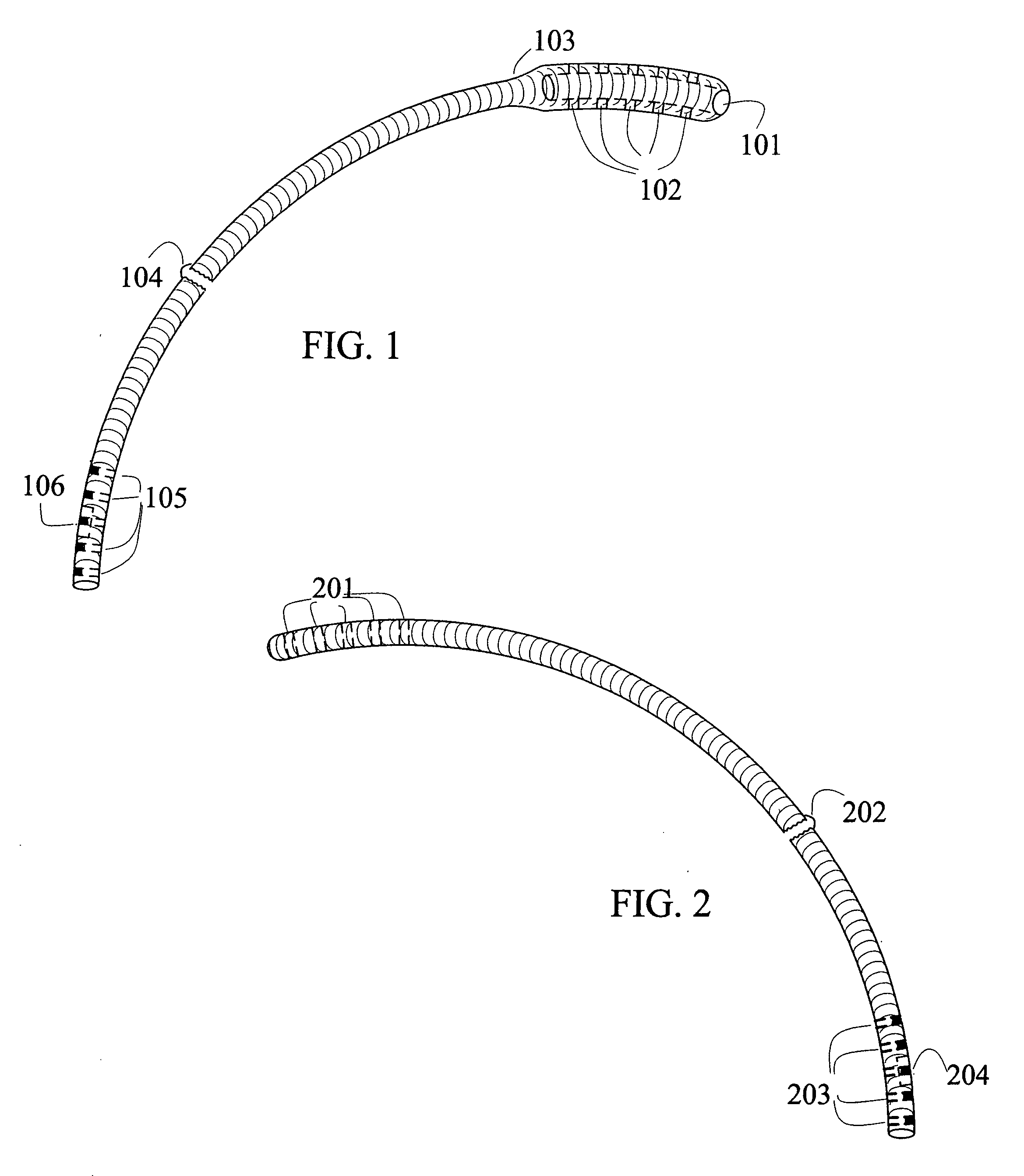
[0031]Figure one illustrates the female plate components of the Less Invasive, Multi-Holed, Variable Positioned Locked Pelvic Stabilization System. The device is a smoothly arcing, circular rod made from typical metallic materials common to orthopedic devices such as stainless steel and titanium alloys. The medial end of the device expands (103) to a radius greater than that of the remaining rod section to allow interconnection with the male component of the plate system. At the medial end of the female plate, a circular opening (101) leading to a hollow section with the rod allows the male plate to interconnect with the female plate. Multiple screw holes run through the hollow, interlocking region of the female plate (102). The screw holes (102) may be of a standard configuration, a locking configuration or a variable angled, locking configuration. The overall length of the rod will be variable so as to better match the anatomical dimensions of a given patient (104). The distal end...


PUM


Abstract

Disclosed are an apparatus and its associated method for minimally invasive stabilization of anterior pelvic fractures. The pelvic stabilization system consisting of two rod shaped implants that may be surgically inserted subcutaneously or along the bone surface of each hemipelvis and a means of both linking the individual rods as well as rigidly securing the construct to the pelvis.

Description


Claims


Application Information

Patent Timeline
Owner PARSELL DOUGLAS ERIC
Why Eureka
Try Eureka