
Circular Stapler Buttress

Active Publication Date: 2008-07-03
WL GORE & ASSOC INC
View PDF4 Cites 215 Cited by
  • Summary
  • Abstract
  • Description
  • Claims
  • Application Information

AI Technical Summary

Benefits of technology

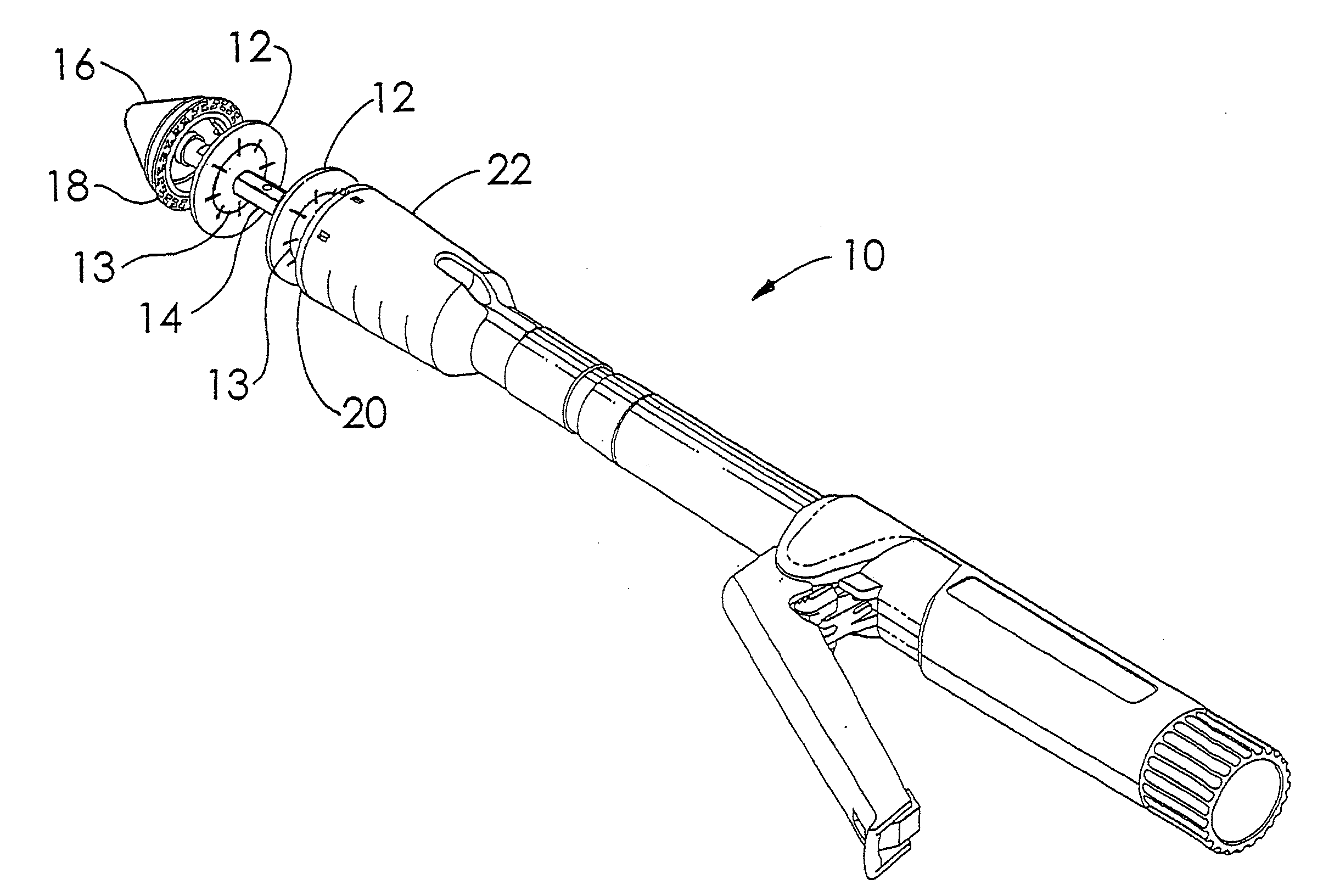
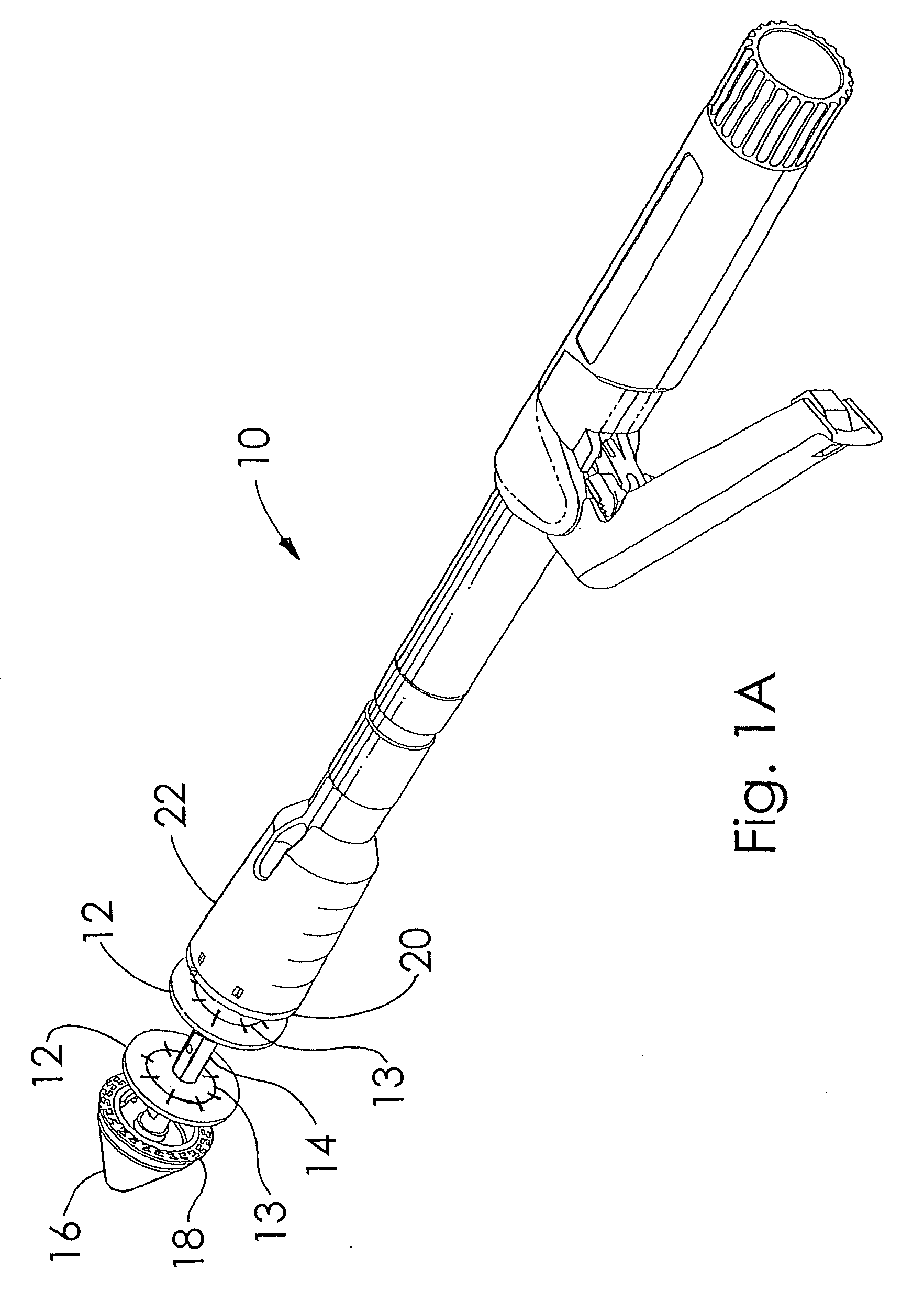
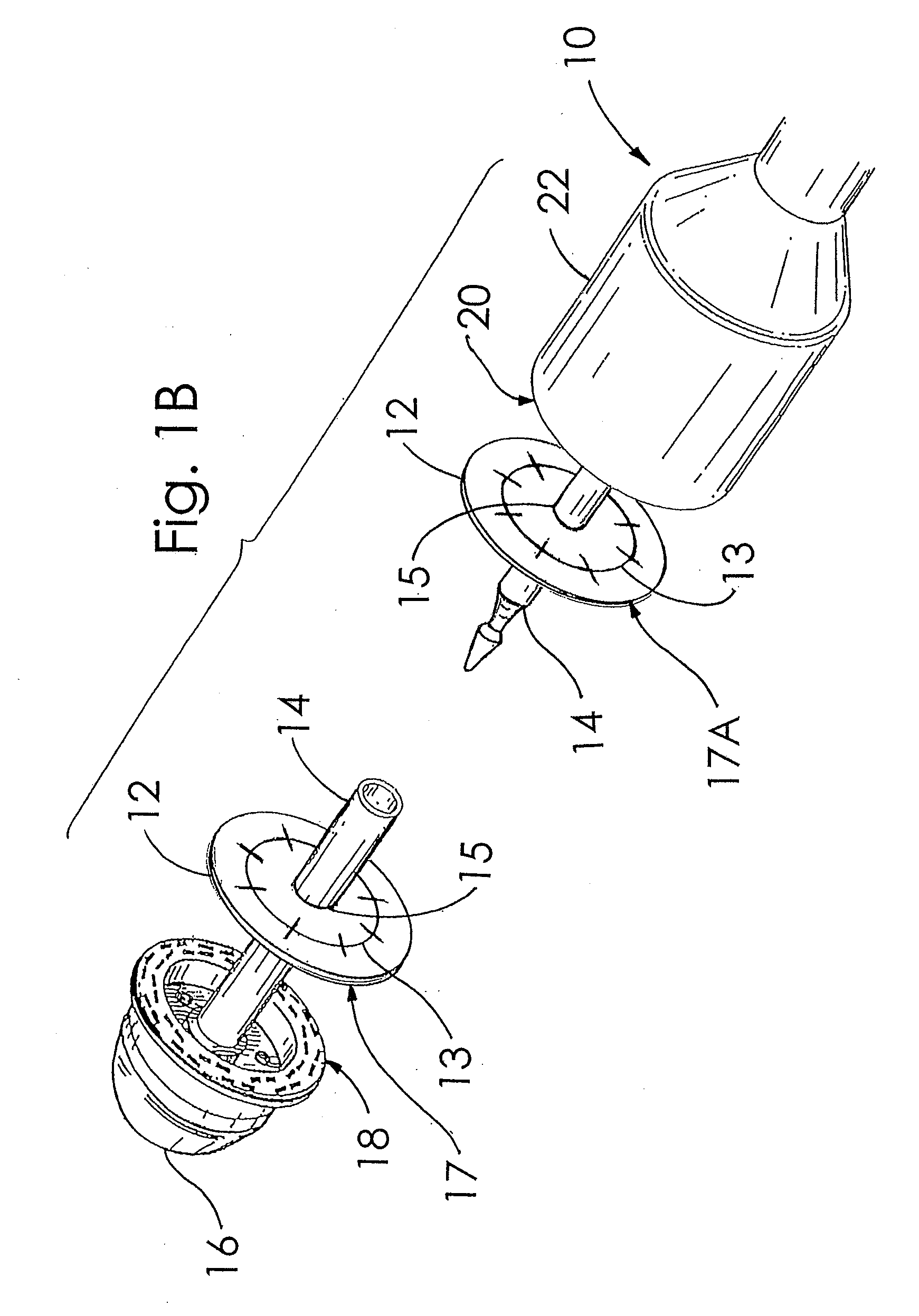
[0009]The present invention is in the form of a buttress reinforcement device for use with circular surgical staplers that does not require an adhesive substance between the buttress and stapler to securely fasten the buttress to the stapler. The present invention is designed with protrusions that extend from the perimeter of the buttress and which may be provided with adhesive. These protrusions are used to align and securely fasten the buttress to the circular stapler body and / or to the circular stapler anvil. Further, these protrusions are disruptably attached, connected, or fastened to the buttress allowing for separation of the protrusions from the buttress in a controlled fashion.
[0010]In a preferred embodiment, when used with a circular surgical stapler, a hole is cut in the central region of the buttress by the stapler's circular cutting blade. The diameter of the hole formed in the buttress by the stapler's circular cutting blade is smaller than the outer diameter of the stapler's anvil. Relief features built into the buttress allow the stapler anvil to pull through the hole created in the buttress by the stapler's circular cutting blade without causing substantial permanent alteration to the buttress. These relief features can be provided regardless of whether the buttress is made of inelastic or elastic materials.
[0012]In one embodiment, the buttress can have a retaining ring, disk, or similar device within or around its central region with a central opening. This retaining ring, disk, or similar device can be used to aid in the retention of the buttress onto the central shaft of the circular stapler without requiring the use of an adhesive substance between the central shaft of the stapler and the buttress construct. The retention of the buttress onto the circular stapler allows for movement, removal, or repositioning of the circular stapler during operation without loss or displacement of the buttress from the stapler.
[0015]Accordingly, one embodiment of the present invention is a reinforcement device for use with a circular stapler that is adapted to create and seal a surgical opening in a patient comprising a buttress adapted for mounting on the circular stapler, the stapler having an anvil that is larger in diameter than the surgical opening that is created by the stapler, wherein following stapling with the stapler, the buttress reinforces the surgical opening created by the stapler in the patient, wherein the buttress includes at least one adaptive opening created by the circular stapler which corresponds to the surgical opening in the patient, said adaptive opening when circular having a diameter smaller than the diameter of the anvil, and wherein the adaptive opening in the buttress allows the anvil to be removed therethrough without causing permanent alteration to the buttress.

Problems solved by technology

Further, these protrusions are disruptably attached, connected, or fastened to the buttress allowing for separation of the protrusions from the buttress in a controlled fashion.

Method used


Image

  • Circular Stapler Buttress
  • Circular Stapler Buttress
  • Circular Stapler Buttress

Examples


example 1

[0072]In order to evaluate the compatibility of buttresses of the present invention with circular staplers, two buttresses of 67% PGA:33% TMC (w / w) having a web density of about 0.5 g / cc were made. These buttresses were made to have a circular shape with an outside diameter of approximately 30 mm, for use with a circular stapler (ILS 29 mm, Ethicon Endosurgery, Somerville N.J.). The buttresses were of uniform thickness of about 0.25 mm, and were provided with a center hole of about 6.3 mm diameter. The central region of each buttress was also provided with a circular silicone stiffener having a diameter of about 19.1 mm and a thickness of about 0.5 mm. Each of these stiffeners was provided with a 6.3 mm diameter hole at its center. One stiffener was adhered to one side of each buttress with the center holes through each component aligned, using MED-1356 silicone adhesive, Nusil technologies, Carpenteria Calif.

[0073]A 30 cm section of porcine colon was obtained and cut in half; purse...

example 2

[0075]A preferred embodiment of a buttress with protrusions was made of 67% PGA: 33% TMC (w / w) having a web density of about 0.5 g / cc. using the following method. Two acrylic sheets, each approximately 1.6 mm thick were securely taped with duct tape onto a laser table that had perforations to allow for fume elimination and with a cutting head that was motion controlled by computer. The acrylic sheets were cut with a laser (Laser Machining Incorporated, Model C-42, Somerset, Wis.) into a first pattern as shown in FIG. 9A. A first laser cut was made describing this pattern followed by a second laser cut in the same pattern to insure that both acrylic sheets were cut completely through. The laser cut pieces of acrylic material were then removed from the remainder of the acrylic sheet which was still attached to the laser cutting table by duct tape.

[0076]A piece of double coated medical tape with silicone release coating on both sides of the bleached Kraft paper covering both sides of t...


PUM

PropertyMeasurementUnit
diameteraaaaaaaaaa
w/waaaaaaaaaa
thicknessaaaaaaaaaa

Abstract

A buttress for use with circular surgical staplers that does not require adhesive to securely fasten the buttress to the stapler. Following cutting and stapling by the circular stapler, the buttress has an adaptive opening through its central region with a diameter smaller than the outer diameter of the stapler anvil. Because of relief features built into the buttress, the stapler anvil may be pulled through the buttress material without causing permanent alteration to the buttress. These relief features may be provided regardless of whether the buttress is made of inelastic or elastic materials. The buttress is generally circular in shape with an outer diameter sized to coincide with the outer diameter of the stapler body staple compression surface and the outer diameter of the anvil compression surface of a circular stapler with which it is used. Prior to surgical use, the buttress is attached to the stapler with disruptable portions extending from outer perimetal areas of the buttress.

Description

CROSS REFERENCE TO RELATED APPLICATIONS[0001]This application is a continuation of U.S. application Ser. No. 10 / 944,149, filed Sep. 16, 2004, which is a continuation-in-part of co-pending U.S. application Ser. No. 10 / 666,204, filed Sep. 17, 2003, which is incorporated herein by reference.FIELD OF THE INVENTION[0002]The present invention relates to the field of surgical buttresses.BACKGROUND OF THE INVENTION[0003]A circular stapler is one device that can be used in surgical applications for the joining of body tissue. In the area of surgical anastomotic stapling, it can be used for joining pieces of tissue in a manner such that a continuous pathway, lumen, or surgical opening, is formed after the tissue is stapled together. This lumen is formed when a circle of staples is used to join two pieces of tissue after which the tissue interior to the innermost circle of staples is cut out by a concentric circular retractable blade. Retraction of the circular stapler removes the cut tissue t...

Claims


Application Information

Patent Timeline
Patent Type & Authority Applications(United States)
IPC IPC(8): A61B17/04A61B17/072A61B17/08A61B17/115
CPCA61B17/072A61B2017/07257A61B17/115A61B17/07292
Inventor BAUMAN, ANN M.BROYLES, STUART E.CRAWLEY, JERALD M.DAUGHERTY, JOHN R.PIH, NORMAN
Owner WL GORE & ASSOC INC
Learn More