Adherence concepts for non-woven absorbable felt buttresses

a technology of absorbable felt and adherence, which is applied in the direction of surgical staples, manufacturing tools, surgery, etc., can solve the problem of reducing the benefits of having the entire staple line reinforced by the buttress material

Inactive Publication Date: 2014-08-28
TYCO HEALTHCARE GRP LP
View PDF11 Cites 867 Cited by
  • Summary
  • Abstract
  • Description
  • Claims
  • Application Information

AI Technical Summary

Benefits of technology

[0034]According to a further aspect of the present disclosure, a surgical stapling apparatus is provided and includes a housing; a handle supported by the housing; an elongated body extending distally from the housing; and a tool assembly at the distal end of the elongated body. The tool assembly includes a cartridge assembly including a cartridge having a plurality of surgical fasteners therein, and an anvil assembly in juxtaposed relation to the cartridge assembly, at least one of the cartridge assembly and anvil assembly being movable in relation to the other of the cartridge assembly and anvil assembly. The anvil assembly includes an anvil plate defining a pair of opposed distal side slots for receiving an end of an anchor and a pair of opposed proximal side slots for receiving an end of an anchor. The anvil plate includes at least one of the following: at least one of the pair of distal side slots is keyhole-shaped; and at least one of the pair of proximal side slots is keyhole-shaped. The surgical stapling apparatus further includes a surgical buttress releasably secured to a tissue contacting surface of at least one of the anvil plate and the staple cartridge, wherein each surgical buttress is secured to the at least one of the anvil assembly and the cartridge assembly by at least one anchor; a release assembly associated with the at least one of the anvil assembly and the cartridge assembly; and a drive assembly slidably translatable through the tool assembly from a proximal position to a distal position, the drive assembly actuating the release assembly to thereby release the anchor and to free the surgical buttress from the at least one of the anvil assembly and cartridge assembly.
[0035]According to yet another aspect of the present disclosure, a loading unit for use with a surgical stapling apparatus is provided. The loading unit comprises a tool assembly having a cartridge assembly including a cartridge having a plurality of surgical fasteners therein, and an anvil assembly in juxtaposed relation to the cartridge assembly, at least one of the cartridge assembly and anvil assembly being movable in relation to the other of the cartridge assembly and anvil assembly. The anvil assembly includes an anvil plate defining a pair of opposed distal side slots for receiving an end of an anchor and a pair of opposed proximal side slots for receiving an end of an anchor. The anvil plate includes at least one of the following: at least one of the pair of distal side slots is keyhole-shaped; and at least one of the pair of proximal side slots is keyhole-shaped. The loading unit further includes a surgical buttress releasably secured to a tissue contacting surface of at least one of the anvil plate and the staple cartridge, wherein each surgical buttress is secured to the at least one of the anvil assembly and the cartridge assembly by at least one anchor; a release assembly associated with the at least one of the anvil assembly and the cartridge assembly; and a drive assembly slidably translatable through the tool assembly from a proximal position to a distal position, the drive assembly actuating the release assembly to thereby release the anchor to free the surgical buttress from the at least one of the anvil assembly and cartridge assembly.

Problems solved by technology

If the shifting of the buttress material is pronounced and is not corrected by the surgeon before firing the surgical stapling apparatus, then staples may form outside the perimeter or width of the buttress material thereby reducing the benefits of having the entire staple line reinforced by the buttress material.

Method used


Image

  • Adherence concepts for non-woven absorbable felt buttresses
  • Adherence concepts for non-woven absorbable felt buttresses
  • Adherence concepts for non-woven absorbable felt buttresses

Examples


Embodiment Construction

[0098]Embodiments of the presently disclosed surgical stapling apparatus and loading unit will now be described in detail with reference to the drawings, in which like reference numerals designate identical or corresponding elements in each of the several views.

[0099]In the drawings and in the description that follows, the term “proximal”, as is traditional, will refer to the end of the stapling apparatus which is closest to the operator, while the term “distal” will refer to the end of the apparatus which is furthest from the operator.

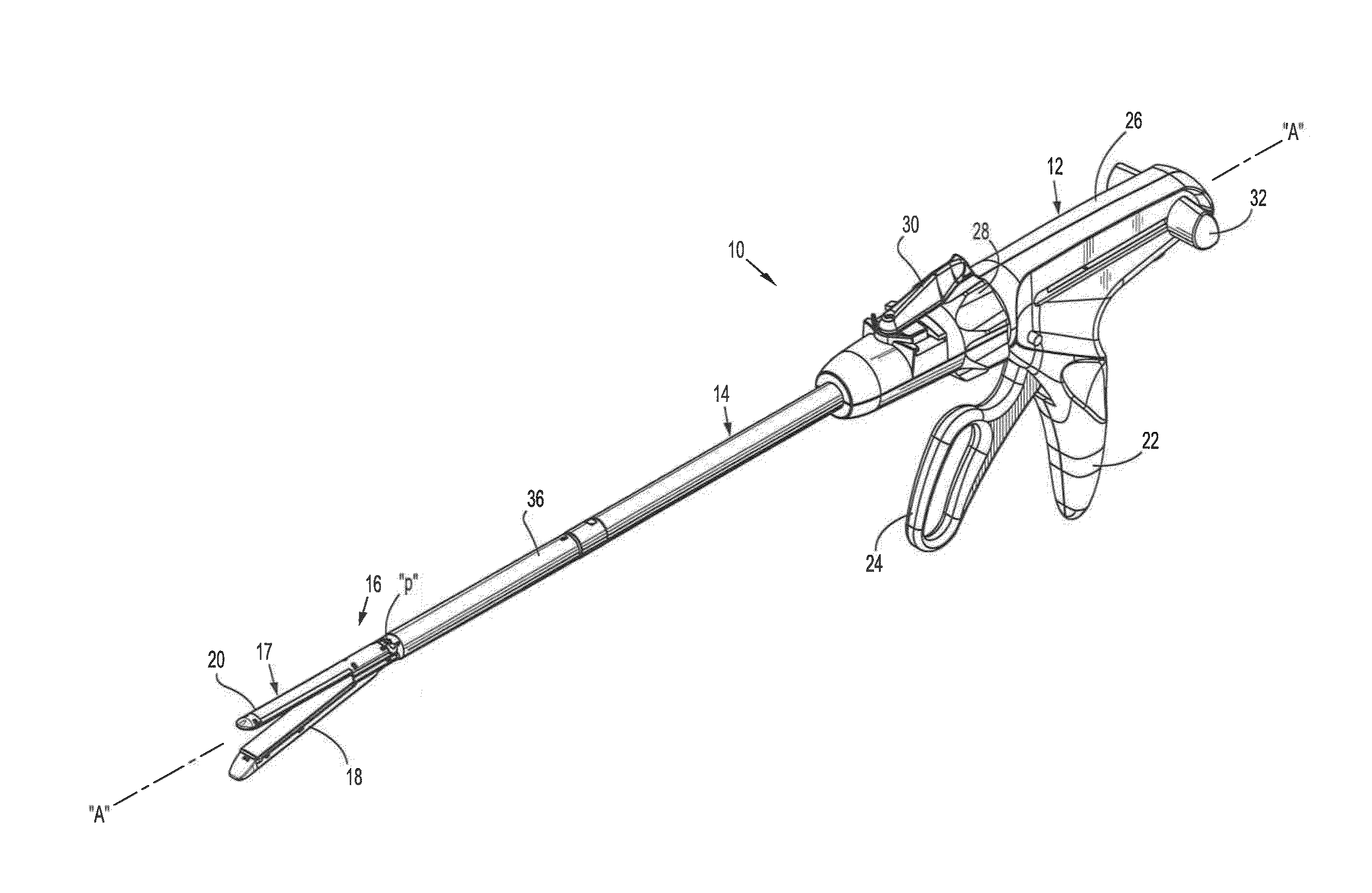
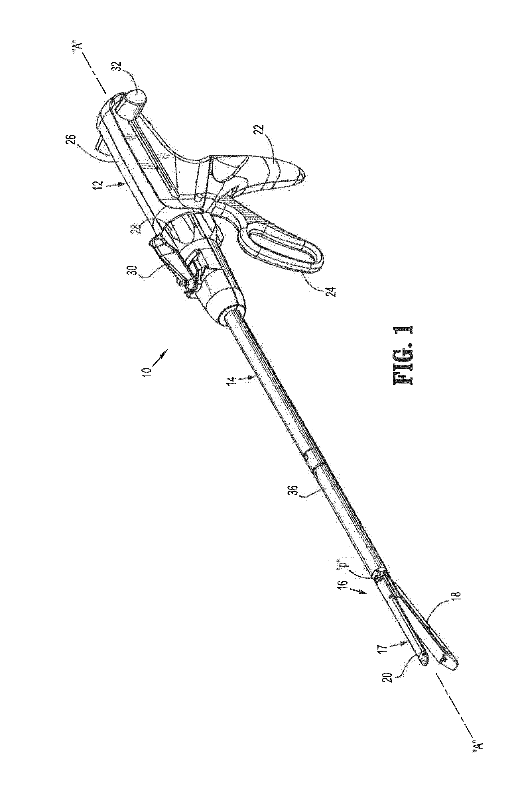
[0100]FIG. 1 shows a surgical apparatus, e.g., surgical stapling apparatus, generally referred to as 10. In the interest of brevity, this disclosure will focus primarily on to the tool assembly of the surgical stapling apparatus 10. A detailed discussion of the remaining components and method of use of surgical stapling apparatus 10 is disclosed in U.S. Pat. No. 6,241,139, the disclosure of which is hereby incorporated by reference herein.

[0101]Surgic...


PUM

PropertyMeasurementUnit
lengthaaaaaaaaaa
lengthsaaaaaaaaaa
areaaaaaaaaaaa

Abstract

A loading unit for use with a surgical stapling apparatus including a tool assembly and a surgical buttress. The tool assembly includes: a cartridge assembly including a staple cartridge having a tissue facing surface, staple retaining pockets having a plurality of surgical fasteners therein, and a knife slot; and an anvil assembly including an anvil plate having a tissue facing surface defining staple forming pockets and a knife slot. The surgical buttress is attached to the tissue facing surface of at least one of the cartridge assembly or the anvil assembly, and conforms to the tissue facing surface such that the surgical buttress is deformed locally into the staple retaining pockets and the knife slot of the cartridge assembly or the staple forming pockets and the knife slot of the anvil assembly to which the surgical buttress is attached.

Description

CROSS-REFERENCE TO RELATED APPLICATION[0001]The present application claims the benefit of, and priority to, U.S. Provisional Application No. 61 / 770,855, filed on Feb. 28, 2013 the entire disclosure of which is incorporated by reference herein.[0002]The present application relates to U.S. patent application Ser. No. 13 / 729,144, filed on Dec. 28, 2012, now U.S. Pat. No. 8,631,989, which is a Continuation Application which claims the benefit of and priority to U.S. application Ser. No. 13 / 097,194, filed on Apr. 29, 2011, now U.S. Pat. No. 8,365,972, which is a Continuation-In-Part Application which claims the benefit of and priority to U.S. application Ser. No. 12 / 414,943, filed on Mar. 31, 2009, now U.S. Pat. No. 8,011,550, the entire content of each of which is incorporated herein by reference.BACKGROUND[0003]1. Technical Field[0004]The present disclosure relates to a surgical apparatus having a buttress material incorporated therewith. More particularly, the present disclosure relat...

Claims


Application Information

Patent Timeline
Patent Type & Authority Applications(United States)
IPC IPC(8): A61B17/072
CPCA61B17/072A61B17/07292A61B2017/00004A61B2017/00477A61B2017/07257A61B2017/07271Y10T29/49908A61B17/07207
Inventor HODGKINSON, GERALDSCIRICA, PAUL A.
Owner TYCO HEALTHCARE GRP LP
Why Eureka
Try Eureka