
Barb clamp with smooth bore

a tubular body and bar clamp technology, applied in the direction of hose connections, adjustable joints, pipe joints, etc., can solve problems such as the growth of harmful bacteria

Active Publication Date: 2008-07-17
SAINT GOBAIN PERFORMANCE PLASTICS CORP
View PDF53 Cites 38 Cited by
  • Summary
  • Abstract
  • Description
  • Claims
  • Application Information

AI Technical Summary

Benefits of technology

The technical effect of this patent is that it describes how the end of a pipe has been designed to gradually narrow down to its final size without any sudden changes or gaps where air could get inside. This helps keep the pressure even across the entire system, which ensures safe and reliable performance.

Problems solved by technology

The technical problem addressed by this patent is how to create safe and leak-proof connections when using flexible tubing in different environmental settings, particularly in the medical and pharmaceutical industries where there is an absolute requirement to prevent fluids from entering the connecting points.

Method used


Image

  • Barb clamp with smooth bore
  • Barb clamp with smooth bore
  • Barb clamp with smooth bore

Examples


Embodiment Construction

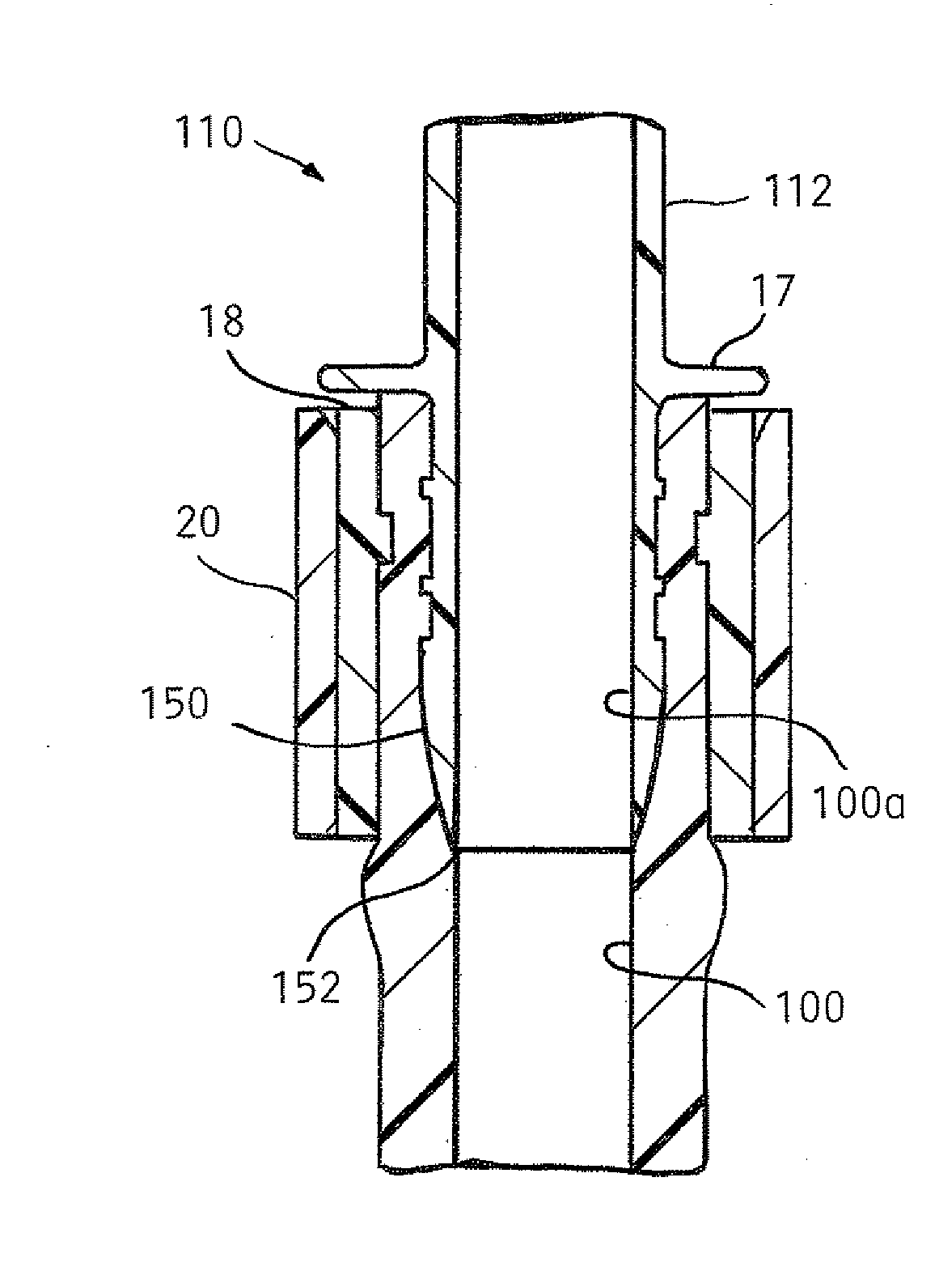
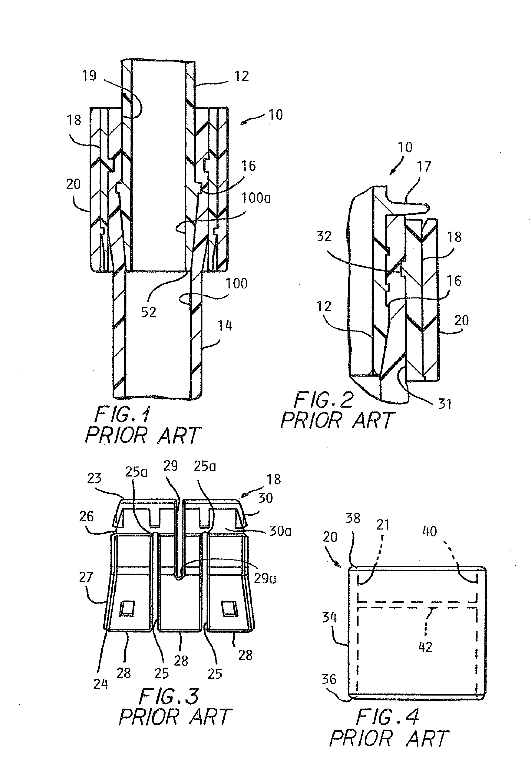
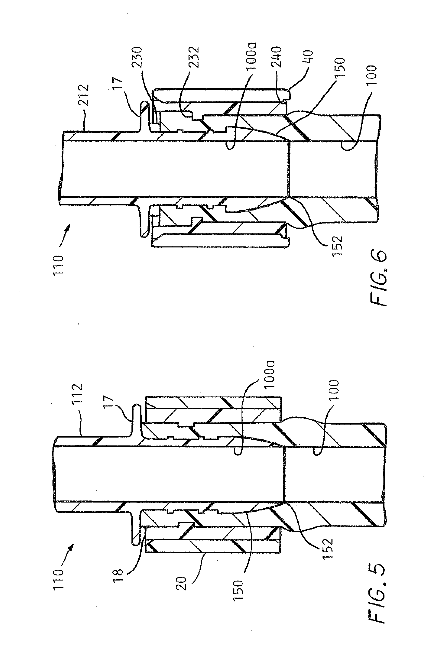
[0019]FIGS. 1 and 2 show the current barb clamp connector 10 for coupling a barbed fitting 12 and a flexible tube 14 and discussed hereafter. The barb fitting 12 is generally made of a non-metal material which allows it to be heat welded to a proprolyene or ethylene medical or pharmaceutical bag. The same and similar materials can be used for biotech, pharmaceutical, medical, and foodstuff fitting connections and manifold applications. The fitting can also be made from other plastics and stainless steel when required. As seen in FIGS. 1 and 2, the barbed fitting 12 may encompass different configurations but will generally include at least one expanded or barbed end 16 for a 360° radial compression connection to the flexible tube 14. If the barb clamp 10 is to be used in a medical or pharmaceutical environment, the barb fitting 12 is preferably made from an FDA. (Food and Drug Administration) approved polypropylene, silicone, TPE, TPR, etc. The barb fitting 12 may also include a flan...


PUM

PropertyMeasurementUnit
Lengthaaaaaaaaaa
Diameteraaaaaaaaaa

Abstract

A barb clamp is provided for fluid liquid or gaseous connection to a flexible tube, the flexible tube having an inner bore defined by a predetermined inner diameter for providing a fluid flow path. The barb clamp includes a barb connector having the same predetermined inner diameter as the flexible tube and a tapered end insertable into the tube. A sleeve and collet lock over the tubing and barb connector to prevent liquid material entering between the barb and tube. The tapered end of the barb connector terminates at a point so that there is no transition between the inner diameter of the tube and the inner diameter of the barb connector to provide no pressure differential in the tube between the outside and inside of the barb clamp.

Description


Claims


Application Information

Patent Timeline
Owner SAINT GOBAIN PERFORMANCE PLASTICS CORP
Features
  • Generate Ideas
  • Intellectual Property
  • Life Sciences
  • Materials
  • Tech Scout
  • Unparalleled Data Quality
  • Higher Quality Content
  • 60% Fewer Hallucinations
Learn More