Field bus interface

a field bus and interface technology, applied in the direction of liquid/fluent solid measurement, ac network voltage adjustment, instruments, etc., can solve the problem of no, or very little, surplus power, and achieve the effect of improving performance and increasing the performance of radar level gauges

Inactive Publication Date: 2008-07-24
ROSEMOUNT TANK RADAR
View PDF4 Cites 24 Cited by
  • Summary
  • Abstract
  • Description
  • Claims
  • Application Information

AI Technical Summary

Benefits of technology

[0019]The performance of a radar level gauges can typically be increased if additional power can be made available. At the same time, RLGs are often arranged in hazardous areas, thus requiring intrinsically safe power supply. The conflict between limited power supply and improved performance can be mitigated by a field bus interface according to an embodiment of the present invention.

Problems solved by technology

In a case where the bus voltage is at, or very close to, the lower limit of the bus voltage range, essentially all available power will be used by the first power supply circuitry and the communication circuitry, resulting in no, or very little, surplus power.

Method used


Image

  • Field bus interface
  • Field bus interface
  • Field bus interface

Examples


Embodiment Construction

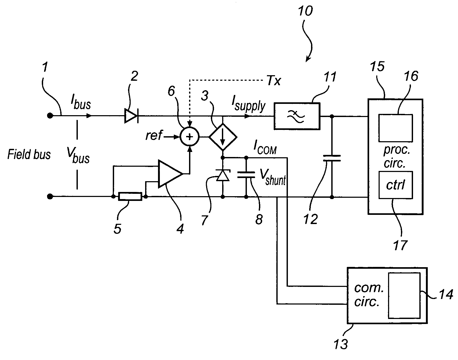
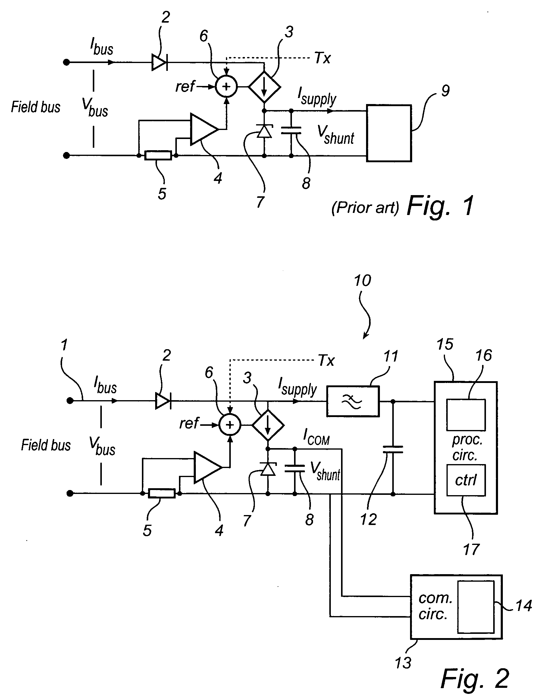
[0025]FIG. 1 shows a field bus interface between an intrinsically safe field bus 1 and a bus powered device 9, such a process instrument. As indicated in FIG. 1, the interface draws a preset average current Ibus from the bus at a voltage Vbus which is allowed to vary within a certain range, e.g. 9-32 V. The interface comprises a diode 2 in series with a controllable current source 3. A current feedback path in the form of an operational amplifier 4 arranged to detect the voltage difference over a resistor 5, is arranged to provide a current feedback signal to an adder 6, where it is subtracted from a current set point (ref). The resulting difference is provided as a control signal (ctrl) to the current source 3. Optionally, the adder 6 is also provided with a timing signal Tx, indicating the timing of an alternating signal current modulated on the bus current.

[0026]Between the output of the current source 3 and the resistor 5 is connected a shunt regulator, here a zener diode 7, in ...


PUM


Abstract

A field bus interface for connecting a device to a field bus, comprising communication circuitry for providing communication via the field bus, first power supply circuitry arranged to provide said communication circuit with a predefined communication power at a predefined drive voltage, and second power supply circuitry arranged to provide a processing circuitry with processing power at said bus voltage only when a power available from said field bus exceeds said communication power.
More specifically, the power provided to the processing circuitry at a given bus current will be decided by the power actually available, instead of a power level decided by the lower limit of the voltage range of the field bus specification. The first circuitry and the communication circuitry will ensure that the field bus requirements are met in a case when the bus voltage falls close to the lower limit of the bus voltage range.

Description

FIELD OF THE INVENTION[0001]The present invention relates to a field bus interface.BACKGROUND OF THE INVENTION[0002]Industrial field buses, e.g. according to IEC 61158-2 (such as Foundation Fieldbus, Profibus Pa.), are increasingly utilized in instrumentation systems. They reduce the cost for installation and cabling, as several devices (nodes) can be connected to the same bus. The bus provides power supply and communication with the devices.[0003]When devices on the bus are installed in hazardous areas, measures must be taken to provide explosion protection. One solution is to ensure intrinsic safety, i.e. to limit currents, voltages and power so as to eliminate the risk of spark ignition.[0004]A consequence of the field bus physical layer requirements is that the devices should draw a predefined current independent of the bus voltage in a specified range, having a lower limit in accordance with the field bus standard, e.g. 9 V. The upper limit is adapted to allow for compensation ...

Claims


Application Information

Patent Timeline
Patent Type & Authority Applications(United States)
IPC IPC(8): H02J3/00
CPCH02J1/00G01F23/284
Inventor JAKOBSSON, ROLANDNILSSON, VALTER
Owner ROSEMOUNT TANK RADAR
Why Eureka
Try Eureka