Jaw advancer connected to bone

a jaw advancer and bone technology, applied in the field of jaw advancers connected to bone, can solve the problems of increasing salivation in the mouth and requiring time to accomplish the forward motion

Inactive Publication Date: 2008-07-24
WILLIAMS MICHAEL O
View PDF3 Cites 26 Cited by
  • Summary
  • Abstract
  • Description
  • Claims
  • Application Information

AI Technical Summary

Benefits of technology

[0014]It is, therefore, the principal object of this invention to provide a device for advancing the lower jaw of a patient in a timely manner without moving the teeth of the patient.

Problems solved by technology

On the other hand, the Frankel device increases the salivation in the mouth and requires time to accomplish the forward movement of a lower jaw.
However, those jaw forwarding forces can, over time, move the teeth themselves.

Method used


Image

  • Jaw advancer connected to bone
  • Jaw advancer connected to bone
  • Jaw advancer connected to bone

Examples


Embodiment Construction

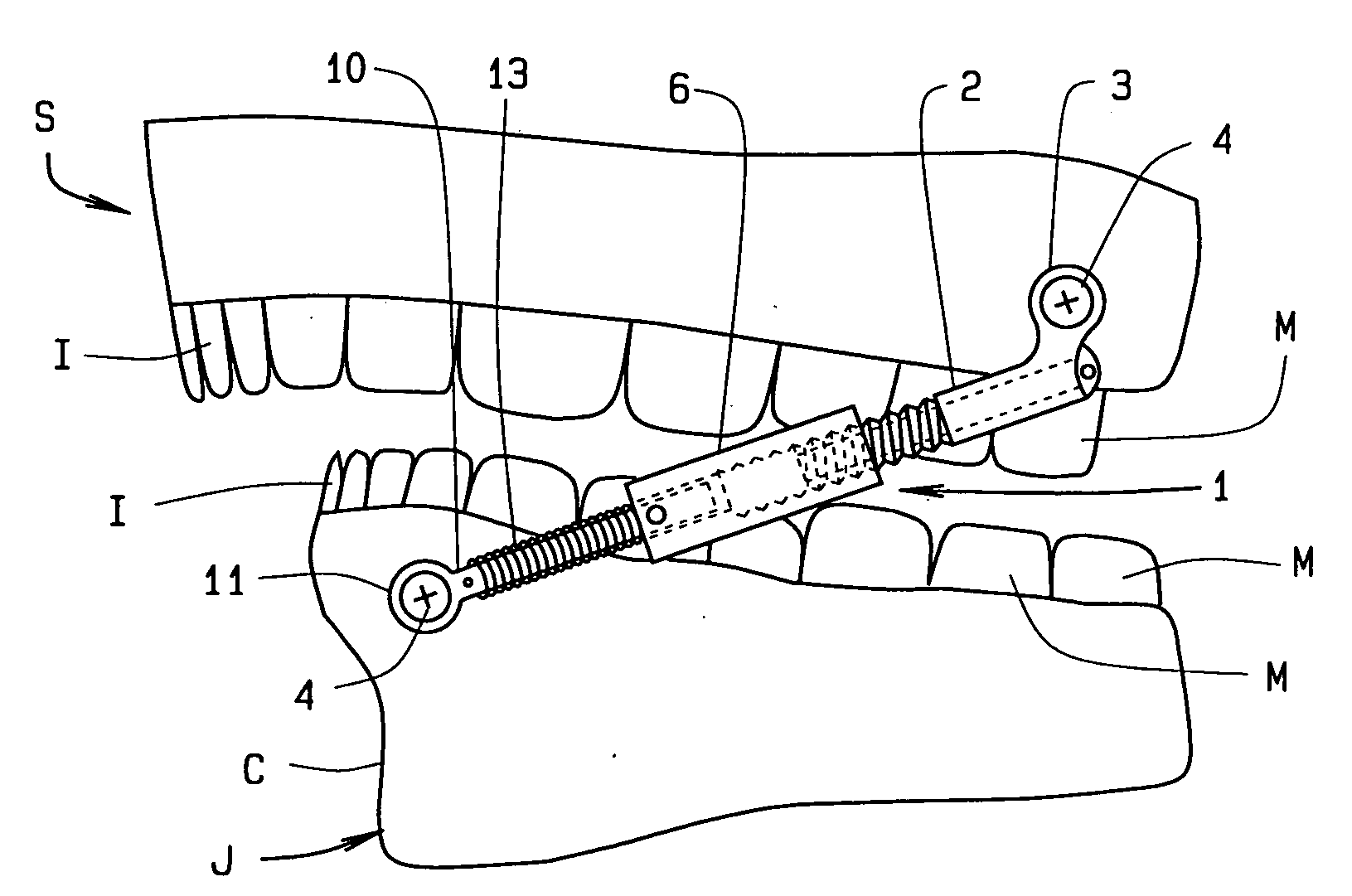
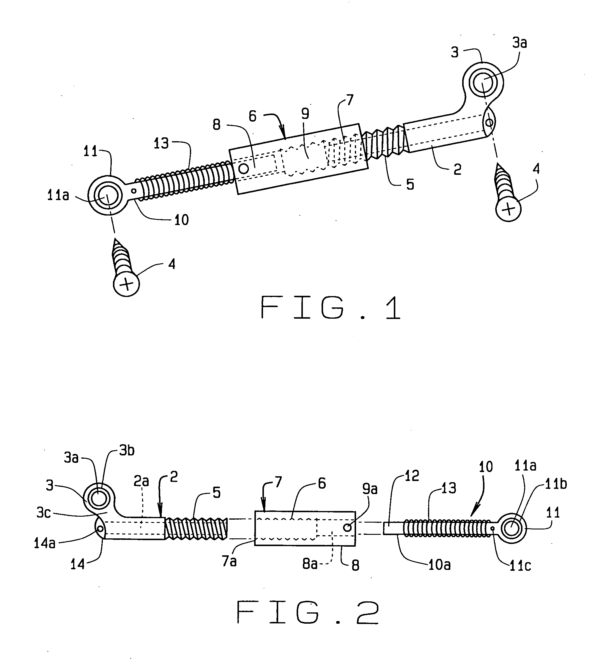
[0026]In referring to the drawings, FIG. 1 shows one jaw advancer 1 of the two required to treat a jaw symmetrically. The jaw advancer has an upper member 2 having an elongated cylindrical shape in the form of an L, when seen from the side. The upper member is generally hollow. The upper member has a head 3 offset and perpendicular to the length of the upper member. The head is generally rounded and has a hole 3a to admit a mechanical fastener, here shown as a screw 4. Opposite the head, the upper member has a threaded end 5.

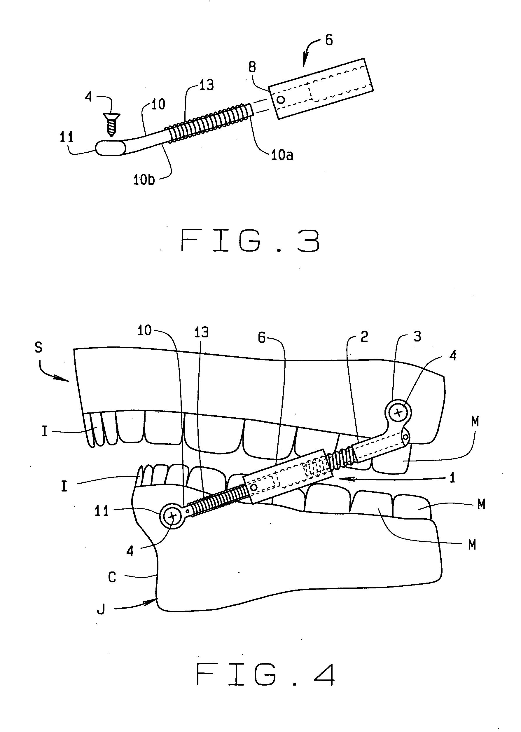
[0027]The advancer then has a socket 6, generally cylindrical in shape and also hollow, with two opposed ends. The socket has a threaded end 7 that cooperatively engages the threaded end of the upper member. Opposite the threaded end, the socket has a smooth bore 8. Upon the surface of the socket, marks 9 assist an orthodontist, or in some cases a patient, in turning the socket which effectively lengthens the advancer to move the jaw forward.

[0028]Opposite the u...


PUM


Abstract

A jaw advancer connects to the skull, maxilla jaw, and the jawbone, mandibular jaw, without contacting the teeth of a patient. Each advancer, of a pair, has a hollow upper member with a head to admit a screw into the maxilla and an opposite threaded end, a socket having a threaded end that admits the upper member and an opposite smooth bore, and a lower member with a head to admit a screw into the mandible and an opposite smooth end that fits into the smooth bore. The lower member has a coaxial spring that provides an expansive force to the lower jaw and that cushions the socket. The lower member slides within the hollow portion of the upper member when the patient moves the advancer. The head of the upper member attaches proximate the molars of the maxilla to advance the mandible and attaches proximate to the incisors of the maxilla to retract the mandible. Alternatively, the lower member has a slight curve to separate it from the teeth.

Description

CROSS REFERENCE TO RELATED APPLICATION[0001]This provisional application claims priority to the non-provisional Ser. No. 60 / 881,330, filed Jan. 19, 2007, which claims priority to the non-provisional application for patent Ser. No. 10 / 439,638 which was filed on Jun. 26, 2006, and to the non-provisional application for patent Ser. No. 10 / 439,638 which was filed on May, 16, 2003 (now U.S. Pat. No. 7,094,051) and are commonly owned by the same inventor. This application is also related to U.S. Pat. No. 5,919,042 commonly owned by the same inventor.BACKGROUND OF THE INVENTION[0002]This invention relates generally to orthodontic appliances for correcting overbite by advancing the lower, or mandible, jaw of a person. And more specifically the invention pertains to a pair of devices connected directly to the upper and lower jaw bones, without using bands or crowns upon teeth, at an angle to advance the mandible forward without moving teeth when the present invention is installed for usage. ...

Claims


Application Information

Patent Timeline
Patent Type & Authority Applications(United States)
IPC IPC(8): A61C3/00
CPCA61C7/36
Inventor WILLIAMS, MICHAEL O.
Owner WILLIAMS MICHAEL O
Why Eureka
Try Eureka