
Child support wedge

a technology for supporting devices and wedges, which is applied in the field of supporting devices, can solve the problems of not providing a means for managing medical devices, child support devices do not provide a means for eliminating or at least minimizing the effect, and do not provide a means for eliminating or minimizing the effect of leg movement or the management of medical devices

Inactive Publication Date: 2008-07-31
KACHTICK ANDERS TRACY
View PDF8 Cites 20 Cited by
  • Summary
  • Abstract
  • Description
  • Claims
  • Application Information

AI Technical Summary

Benefits of technology

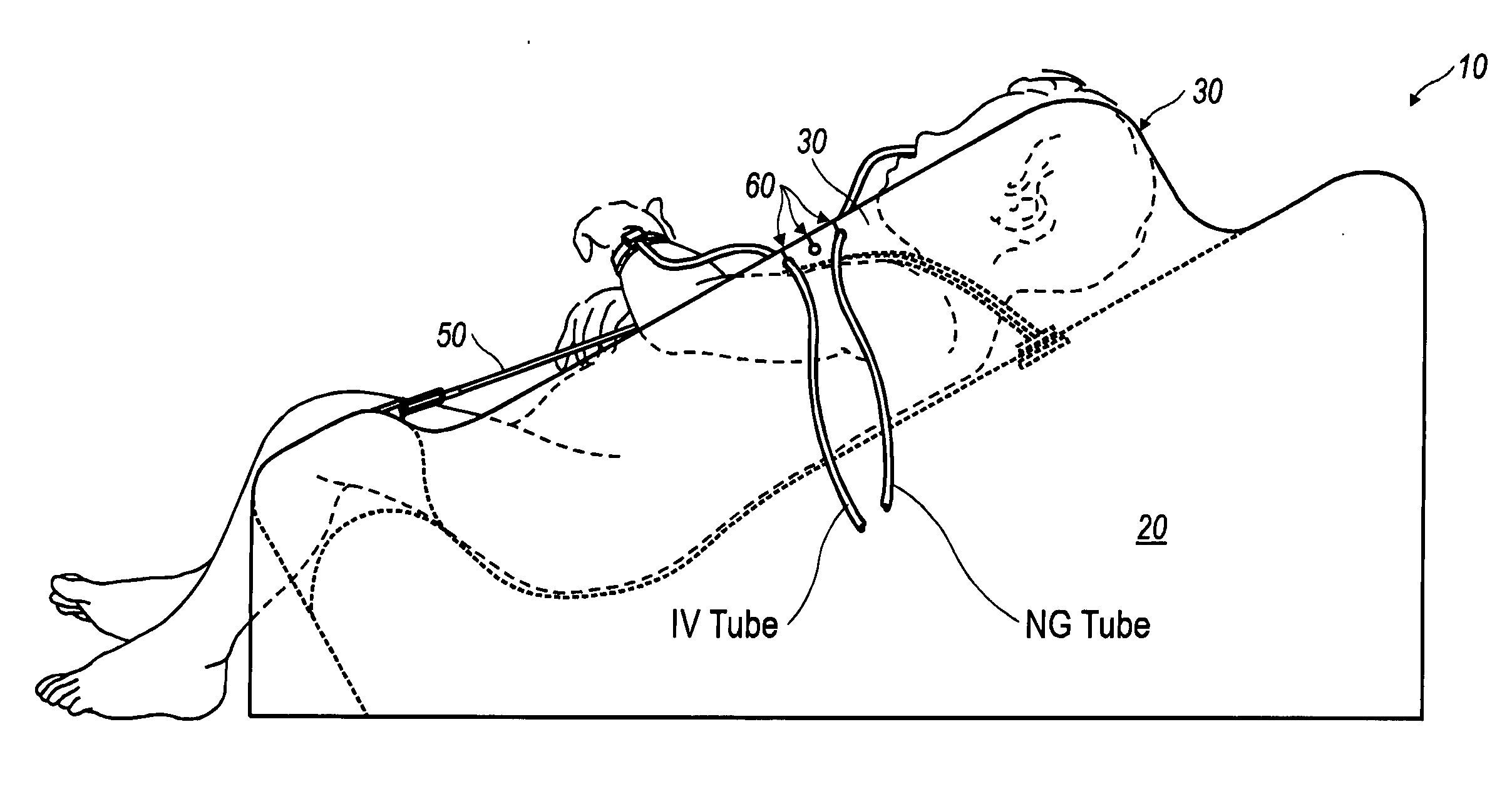
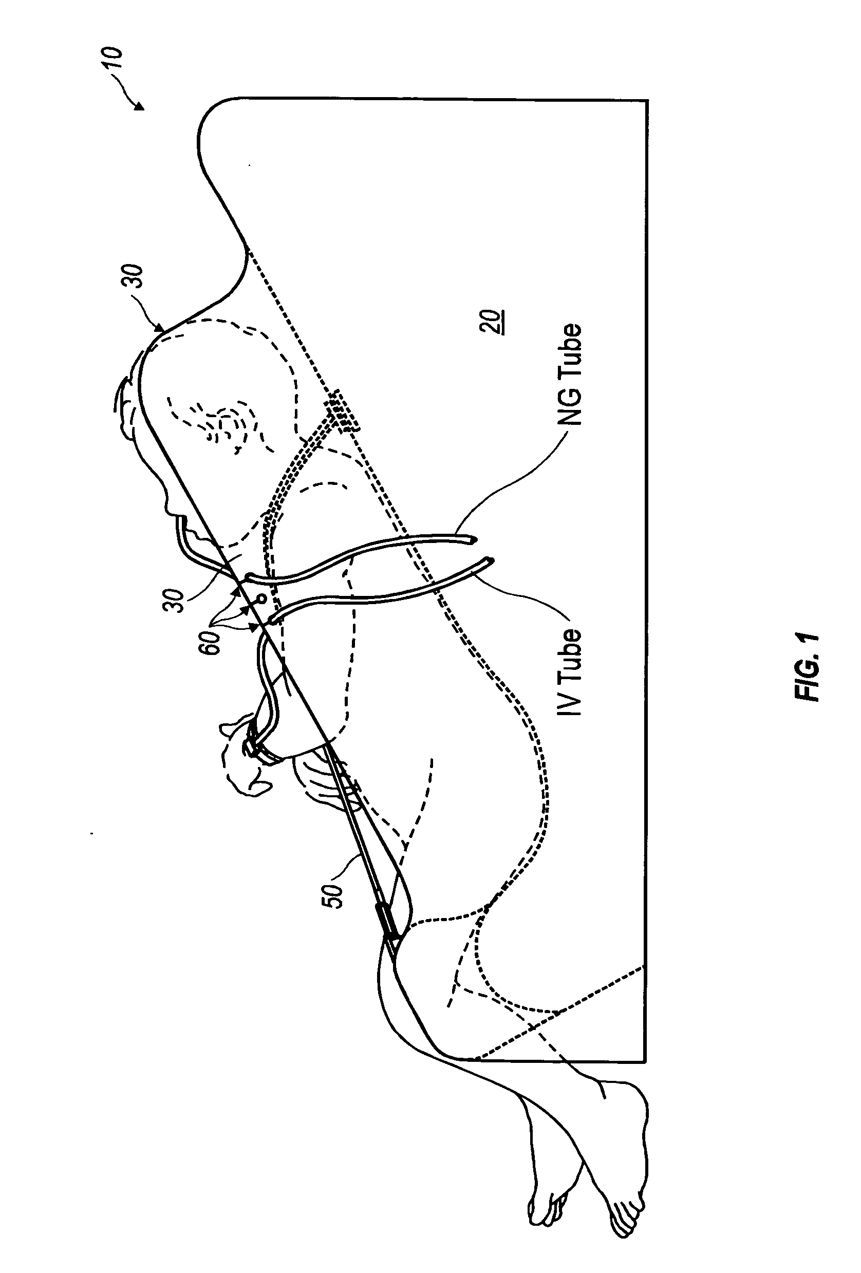
[0008]An object of the present invention is to provide a sturdy, nonabsorbent, child support device capable of securely holding an active child in an supine inclined position with a set of peripherally located side panels and a lower extremity support. A releasable harness fixed to the support device provides further restraint of the inclined supine child. A related object of the present invention is to provide a means to manage medical devices connected to a supported supine child by at least one groove formed in the wedge shaped foundation, side panel and / or lower extremity support.

Problems solved by technology

However, the present child support devices do not provide a means for managing medical devices, such as NG and IV tubes, which may be connected to a child.
Furthermore, such child support devices do not provide a means to eliminate or at least minimize the effect of leg movement.
The patents disclosed below while providing some type of support to a child, do not provide a means to eliminate or at least minimize the effect of leg movement or the management of medical devices.
The prior art devices do not adequately address the problem of providing an effective means of preventing a child from becoming entangled with or pulling out connected medical devices while positioned in a support device.
Nor do the above disclosed devices provide resilient non-absorbent surfaces.
Furthermore, the prior art support devices do not adequately prevent a child's movement in a support device as a result of leg movement.

Method used


Image

  • Child support wedge
  • Child support wedge
  • Child support wedge

Examples


Embodiment Construction

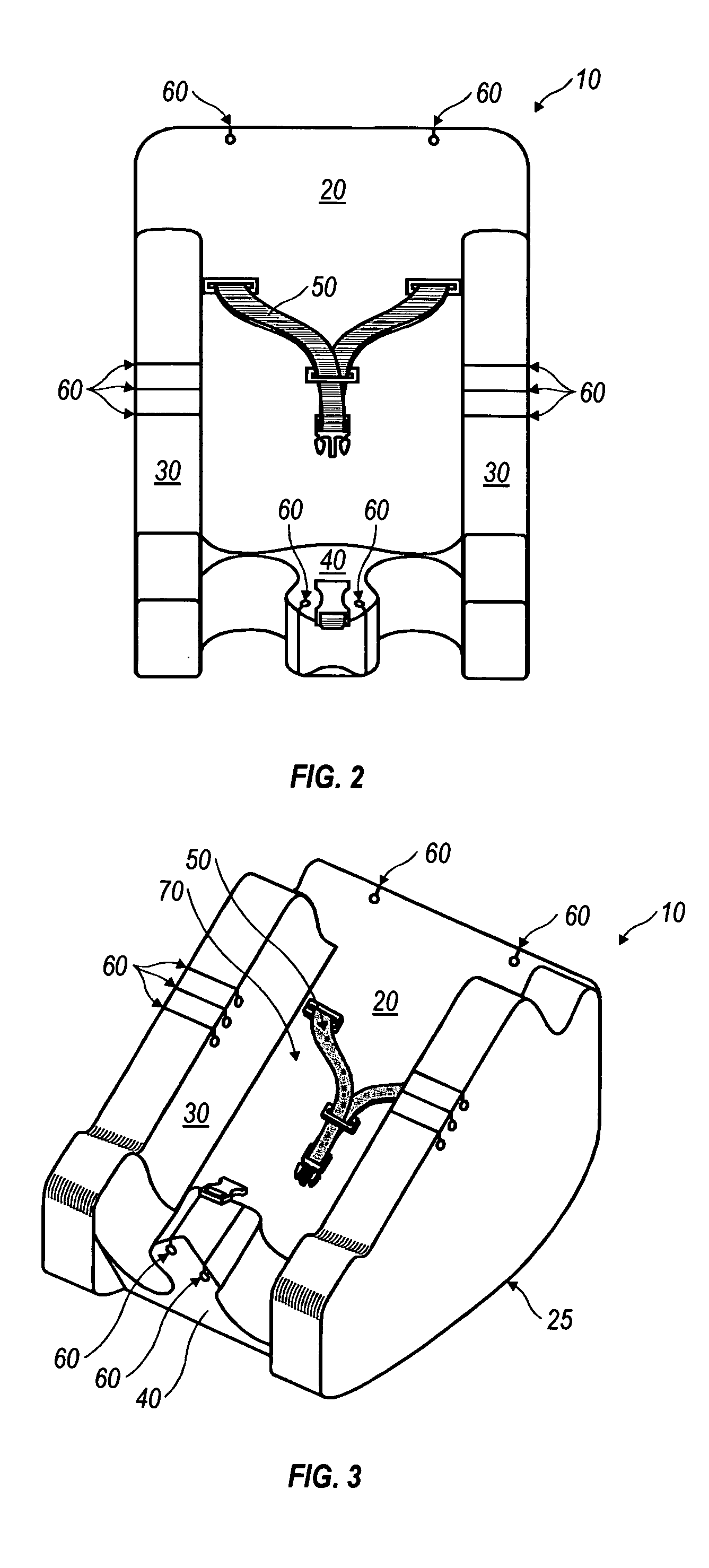
[0013]The present invention includes a wedge shaped foundation 10 with an inclined upper surface 20 formed to support a child in an inclined supine position. At least one side panel 30 projects away from a longitudinal periphery of an inclined upper surface 20. In a preferred embodiment, opposing side panels 30 project from the longitudinal periphery of an inclined upper surface 20 (See FIGS. 1 through 3). An inverted T shaped lower extremity support 40 projects away from a lower region of said inclined upper support surface 20. In a preferred embodiment, the inverted T shaped lower extremity support 40 is positioned between and at a lower end of the opposing side panels 30 (See FIGS. 2 and 3). In such an arrangement, a basin 70 is formed which securely holds a child in a supine inclined position (See FIG. 3).

[0014]A side panel 30 is of sufficient thickness, length and height to prevent a child from sliding, rolling or squirming laterally out of basin 70. Similarly, an inverted T sh...


PUM


Abstract

The present infant or small child support device includes a wedge shaped foundation with an inclined upper surface formed to support a child or small child in an inclined supine position. At least one side panel projects away from a longitudinal periphery of an inclined upper surface. In a preferred embodiment, opposing side panels project from the longitudinal periphery of an inclined upper surface. An inverted T shaped lower extremity support projects away from a lower region of an inclined upper support surface. In a preferred embodiment, an inverted T shaped lower extremity support is positioned between and at a lower end of the opposing side panels to form a basin which securely holds an infant or small child in a inclined supine position. In a preferred embodiment, the present support device is constructed from a resilient non-absorbent material. In yet another embodiment, the present support device can be inflatable.

Description

BACKGROUND OF THE INVENTION[0001]1. Field of the Invention[0002]The present invention relates to supporting devices which provide a surface to support at least a portion of a user's body and particularly to such devices that are particularly constructed, shaped, or sized to support an infant or small child (hereinafter grouped together under the term “child”).[0003]2. Description of the Related Art[0004]Support devices constructed, shaped or sized to support children are typically used to cradle, hold or restrain a child while he or she is not playing or in the arms of a parent or guardian. Currently a number of such child support devices include an inclined surface and a harness restraint system.[0005]However, the present child support devices do not provide a means for managing medical devices, such as NG and IV tubes, which may be connected to a child. Furthermore, such child support devices do not provide a means to eliminate or at least minimize the effect of leg movement. The ...

Claims


Application Information

Patent Timeline
IPC IPC(8): A47C16/00
CPCA47D13/025A61G7/065A61G7/0503A47D13/08A47D15/006
Inventor KACHTICK-ANDERS, TRACY
Owner KACHTICK ANDERS TRACY
Learn More