Antenna device

Inactive Publication Date: 2008-07-31
MITSUMI ELECTRIC CO LTD
View PDF5 Cites 22 Cited by
  • Summary
  • Abstract
  • Description
  • Claims
  • Application Information

AI Technical Summary

Benefits of technology

[0021]According to the second aspect of the invention, the lateral wall of the bracket of the antenna device has the regular-polygon shape including the square shape or the round shape in the horizontal sectional view. Therefore, since the signals of radio waves around the antenna element are uniformly attracted to the lateral wall of the bracket, it is possible to improve the low elevation angle directivity gain in all directions of the antenna element, in addition to the advantage according to the first aspect of t

Problems solved by technology

Accordingly, it is difficult to attach the antenna device to the roof by the use of the magnet or the like.
If a low elevation angle directivity gain of the antenna element is not large, electric waves of the satellite radio may not be sufficiently received.
However, when the roof of the vehicle is made of resin or glass, the roof does not serve as the GND of the antenna element and does not attract the electric waves.
As disclosed i

Method used


Image

  • Antenna device
  • Antenna device
  • Antenna device

Examples


Example

[0029]Hereinafter, an exemplary embodiment of an antenna device according to the invention will be described with reference to the drawings.

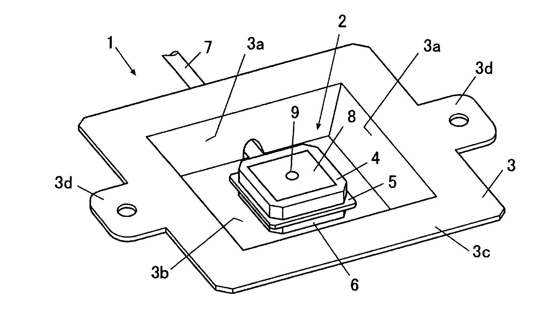
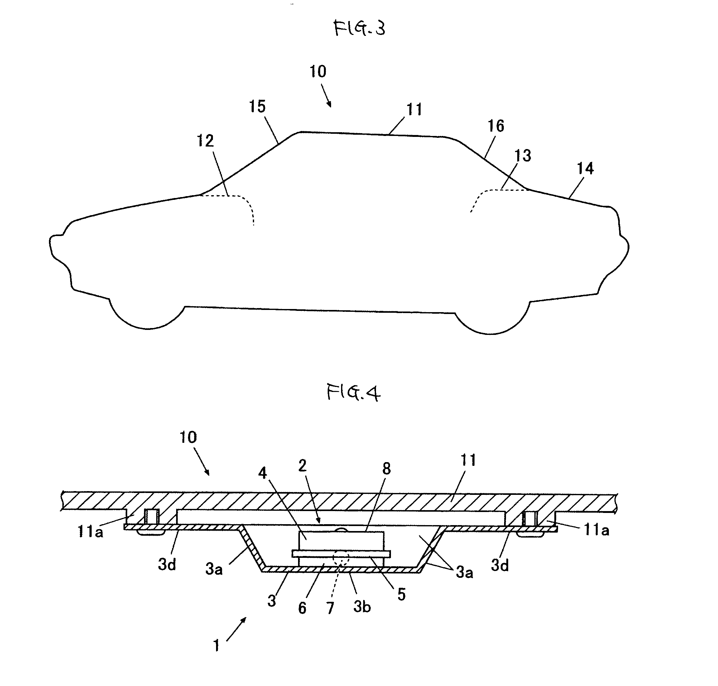
[0030]As shown in FIG. 3, an antenna device 1 according the embodiment is an antenna device attached to a bottom surface of a body made of resin or glass containing glass fiber resin such as glass fiber in a vehicle. As shown in FIG. 1, the antenna device 1 mainly includes an antenna body 2 and a bracket 3.

[0031]As shown in a lateral sectional view of FIG. 2, the antenna body 2 includes an antenna element 4, a circuit board 5, a shield cover 6, a coaxial cable 7, and the like.

[0032]In the embodiment, the antenna element 4 is made of ceramic and has a slightly thick plate shape. A patch-type reception surface 8 as a receiver for receiving radio waves is printed on the top surface of the antenna element 4. FIG. 2 shows the reception surface 8 of the antenna element 4 thicker than an actual one. A GND pattern (not shown) formed of a metallic thin f...


PUM


Abstract

An antenna device attachable to a bottom surface of a resin or glass body of a vehicle, the antenna device includes: an antenna element that has a receiver for receiving radio waves; a circuit board that has a circuit surface having a circuit formed thereon to amplify signals inputted from the antenna element; a shield cover that covers the circuit surface of the circuit board to shield the circuit from interference waves and that is grounded; a coaxial cable that is inserted into the shield cover, that supplies a driving power to the circuit formed on the circuit board, that connects the circuit to a GND, and that outputs signals from the circuit; and a metallic bracket that has a lateral wall surrounding a lateral side of the antenna element and a bottom wall supporting a bottom of the antenna element.

Description

BACKGROUND[0001]1. Technical Field[0002]The present invention relates to an antenna device, and more particularly, to an antenna device mounted on a vehicle having a body made of resin or glass.[0003]2. Related Art[0004]When an antenna device of a GPS system for a vehicle widely used as a positioning system or an antenna device used for a satellite radio coming into practical use in the United States is mounted on a vehicle such as a car, an antenna element stored in a case is installed generally on the outer rear such as a roof of the vehicle (see Patent Documents 1, 2, etc.). In this case, the case of the antenna device may be attached to a metallic roof of the vehicle, for example, by the use of a permanent magnet or the like.[0005]However, the vehicle having a roof made of resin or glass containing glass fiber resin such as glass fiber has been manufactured in recent. Accordingly, it is difficult to attach the antenna device to the roof by the use of the magnet or the like. Thus...

Claims


Application Information

Patent Timeline
IPC IPC(8): H01Q1/32
CPCH01Q1/1271H01Q9/0407H01Q1/526
Inventor NORO, JUNICHIKOHNO, SATOSHI
Owner MITSUMI ELECTRIC CO LTD
Why Eureka
Try Eureka