Vacuum tank device for RH refining

A vacuum tank and body technology, which is applied in the field of RH vacuum tank devices, can solve the problems of high construction cost, difficult construction, and high rail surface elevation in the RH refining workshop, so as to improve the service life, facilitate manufacturing and application, and reduce the overall equipment. Elevation effect

Active Publication Date: 2016-07-13
CHINA NAT HEAVY MACHINERY RES INSTCO
View PDF8 Cites 3 Cited by
  • Summary
  • Abstract
  • Description
  • Claims
  • Application Information

AI Technical Summary

Problems solved by technology

[0005] The purpose of the present invention is to solve the problem that the height of the vacuum tank is too high and the elevation of the rail surface of the RH refining workshop is too high, resulting in high construction cost and difficult construction

Method used


Image

  • Vacuum tank device for RH refining

Examples


Embodiment 1

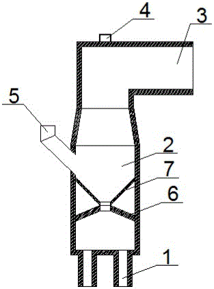
[0021] In order to solve the problem that the height of the vacuum tank is too high and the rail surface of the RH refining workshop is too high, resulting in high construction costs and difficult construction, this embodiment provides the following figure 1 The shown vacuum tank device for RH includes a vacuum tank body 2, the top of the vacuum tank body 2 is connected to a hot bend tube 3, and a top gun channel 4 is opened on the hot bend tube 3, and the bottom end of the vacuum tank body 2 is The dipping tube 1 and the inner cavity of the vacuum tank body 2 are fixedly equipped with a tapered splash-proof cover 6. The bottom end of the splash-proof cover 6 is welded on the inner wall of the vacuum tank body 2 along the circumferential direction, and a through hole is opened in the center of the top end. The central axis of the through hole coincides with the central axis of the top gun channel 4;

[0022] The inner cavity of the vacuum tank body 2 is also fixed with a blank...

Embodiment 2

[0028] This example provides figure 1 The shown vacuum tank device for RH includes a vacuum tank body 2, the top of the vacuum tank body 2 is connected to a hot bend tube 3, and a top gun channel 4 is opened on the hot bend tube 3, and the bottom end of the vacuum tank body 2 is The dipping tube 1 and the inner cavity of the vacuum tank body 2 are fixedly equipped with a conical splash-proof cover 6. The bottom end of the splash-proof cover 6 is welded on the inner wall of the vacuum tank body 2 along the circumferential direction, and a through hole is opened at the top end. The central axis of the hole coincides with the central axis of the top gun channel 4;

[0029] The inner cavity of the vacuum tank body 2 is also fixed with a feeding funnel 7, the top of the feeding funnel 7 is welded on the inner wall of the vacuum tank body 2 along the circumferential direction, and the bottom end is provided with a through hole, which is connected with the splash-proof cover The coa...

Embodiment 3

[0034] This example provides figure 1 The shown vacuum tank device for RH includes a vacuum tank body 2, the top of the vacuum tank body 2 is connected to a hot bend tube 3, and a top gun channel 4 is opened on the hot bend tube 3, and the bottom end of the vacuum tank body 2 is The dipping tube 1 and the inner cavity of the vacuum tank body 2 are fixedly equipped with a conical splash-proof cover 6. The bottom end of the splash-proof cover 6 is welded on the inner wall of the vacuum tank body 2 along the circumferential direction, and a through hole is opened at the top end. The central axis of the hole coincides with the central axis of the top gun channel 4;

[0035] The inner cavity of the vacuum tank body 2 is also fixed with a feeding funnel 7, the top of the feeding funnel 7 is welded on the inner wall of the vacuum tank body 2 along the circumferential direction, and the bottom end is provided with a through hole, which is connected with the splash-proof cover The coa...


PUM


Abstract

The invention provides a vacuum tank device for RH refining.The vacuum tank device comprises a vacuum tank body.A conical anti-splash cover is fixedly mounted in the inner cavity of a vacuum tank body.A through hole is formed in the top end of the anti-splash cover.A discharge funnel is further fixed in the inner cavity of the vacuum tank body.A through hole is formed in the bottom end of the discharge funnel.An alloy chute is connected to the outer wall of the vacuum tank body.The alloy chute is located above the discharge funnel and communicated with the inner cavity of the vacuum tank body.The vacuum tank device has the advantages that the anti-splash cover is added to prevent molten steel splashing, damage, caused by the molten steel splashing, of subsequent air extraction equipment is avoided favorably, and the height of the vacuum tank body is further lowered greatly; impact on the wall of the vacuum tank body during alloy slag adding can be lowered favorably by adding the discharge funnel, and the service life of the vacuum tank body is further prolonged; the heights of the RH vacuum tank body and matched equipment of the vacuum tank body can be lowered favorably, manufacturing cost can be lowered, the overall equipment elevation of an RH refining workshop is further lowered, and investment cost is lowered.

Description

technical field [0001] The invention belongs to the technical field of RH refining outside the furnace, and in particular relates to a vacuum tank device for RH. Background technique [0002] At present, the RH refining furnace is the main means of vacuum refining of molten steel, and has been widely used in domestic and foreign iron and steel enterprises. However, in the actual design and application process, the elevation of the crane rail surface in the RH refining workshop is too high, resulting in high construction costs and difficult construction, especially in the renovation project of the old factory area. Therefore, the design of the RH refining plant seeking a low orbital surface elevation is one of the issues that the designers of the refining outside the furnace have been paying attention to. [0003] The splash height of molten steel during RH vacuum refining under vacuum conditions depends on the deoxidation of molten steel, generally about 6~10m. In order to...

Claims


Application Information

Patent Timeline
Patent Type & Authority Applications(China)
IPC IPC(8): C21C7/10
CPCC21C7/10
Inventor 焦志远余嘉朱浪涛赵腾张虎
Owner CHINA NAT HEAVY MACHINERY RES INSTCO
Why Eureka
Try Eureka