Railroad Crossing

a technology for railroad crossings and crossings, applied in railway signalling and safety, railway traffic control, railways, etc., can solve the problems of little or no physical attenuation devices, provide passive barriers, and easy failure, and achieve gentleness, edge slope, and not create a hazard to traverse

Inactive Publication Date: 2008-08-07
GHIGLIOTTI JEROME J
View PDF4 Cites 6 Cited by
  • Summary
  • Abstract
  • Description
  • Claims
  • Application Information

AI Technical Summary

Benefits of technology

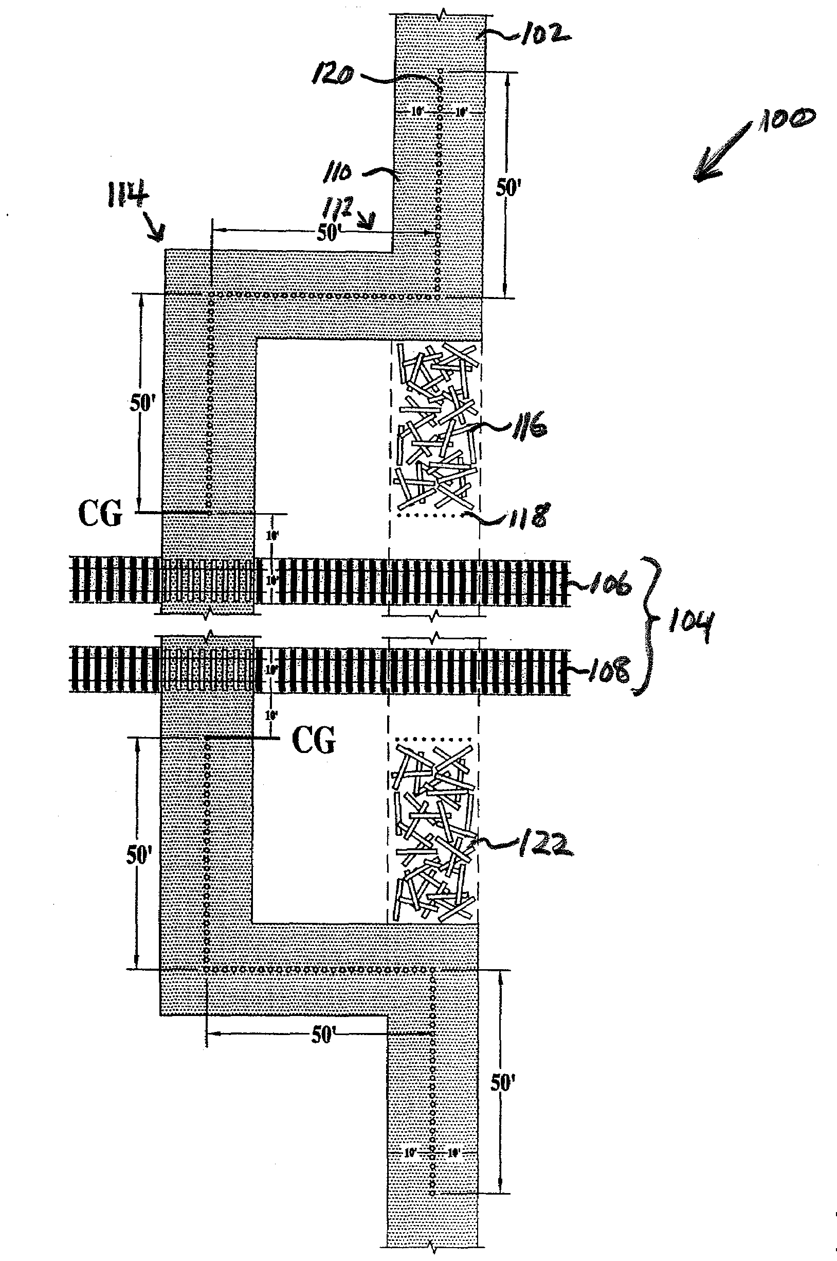
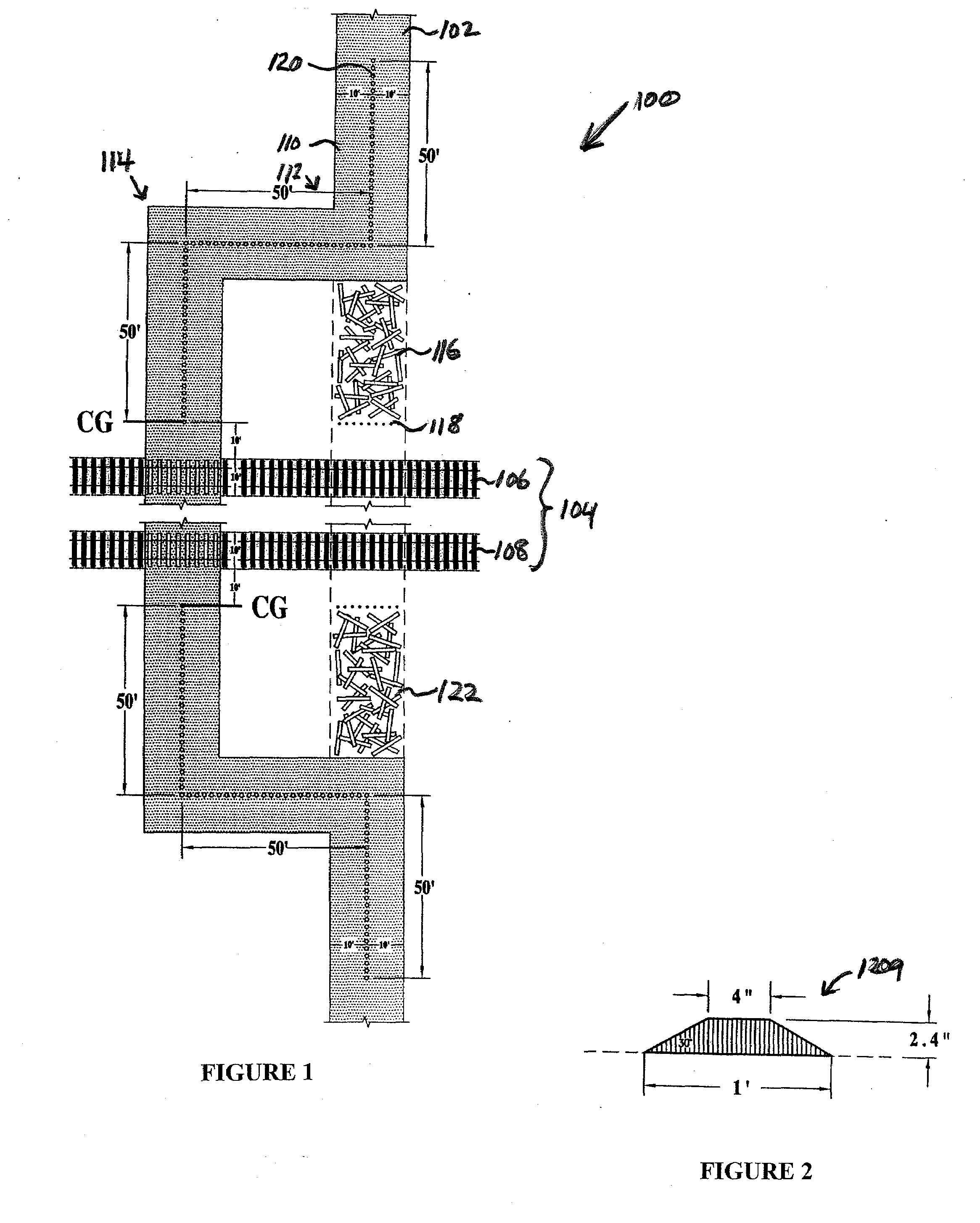
[0003]Approach to an exemplary railroad crossing and progress through it is recognizable by raised, road lane separation discs or otherwise shaped devices, larger (possibly approximately one foot in diameter), in order to distinguish their feel to a motorist driving across them from that of the smaller (approximately four (4) inch diameter) raised road discs and rectangles in use on highways at non-crossing locations. These larger discs or otherwise shaped devices have a gentle, edge slope so as not to create a hazard to traverse. This railroad crossing includes a right angle (ninety (90) degrees) or approximate turn in a road as it approaches the railroad crossing. Extending beyond the end of pavement, at this point, is a ditch or depression, filled to above grade with used wooden railroad ties, which act as an impact attenuation device (vehicle impact attenuation zone) for impaired drivers and vehicles which either did not recognize the crossing approach or were trave

Problems solved by technology

Such systems present little or no physical attenuation devices to alert vehicular traffic to the impending danger at the crossing.
Nor do many present systems provide a passive barrier for the prevention of crossing access

Method used


Image

  • Railroad Crossing
  • Railroad Crossing
  • Railroad Crossing

Examples


Embodiment Construction

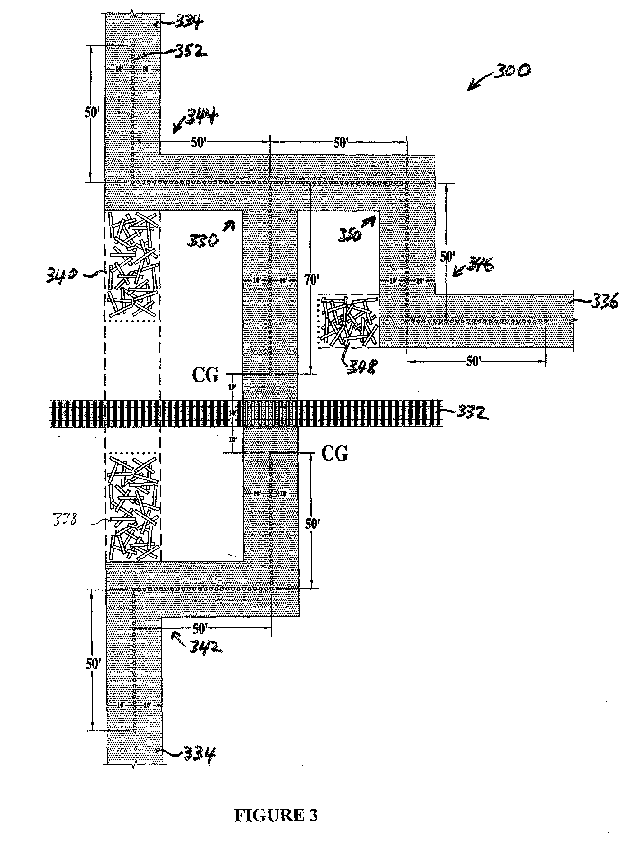
[0013]FIG. 1 shows a railroad crossing 100 according to a first embodiment of the present invention. A road 102 extends in the vertical direction and crosses a railway 104 that extends in the horizontal direction. Two railroad tracks 106, 108 are shown comprising railway 104. In some cases there may be only one railroad track or there may be three or more railroad tracks comprising a railway at a railroad crossing. As a vehicle traveling along road 102 approaches railroad crossing 100 from either direction, it encounters a turn in the road. For example, a vehicle approaching along a first portion 110 of road 102 at the top of FIG. 1 encounters a change in road direction of ninety degrees at a first turn 112. This change in direction requires the vehicle to decelerate. Subsequently, a second turn 114 providing a second change in road direction is encountered. FIG. 1 shows second turn 114 providing a second ninety-degree change in direction. The second change in direction of second tu...


PUM


Abstract

A railroad crossing includes a turn in a road as the road approaches the railroad, the turn forcing an approaching vehicle to slow down. A impact attenuation zone extends from the turn in the direction of traffic flow so that vehicles failing to make the turn enter a vehicle impact attenuation zone are brought to a stop before coming into the area of danger through which railroad trains traverse.

Description

BACKGROUND OF THE INVENTION[0001]This invention relates to railroad crossings and in particular to features used to ensure safety at railroad crossings.[0002]Railroad crossings are common throughout the world. Various systems are in use to ensure the safety of vehicle traffic traveling across railroad crossings. Many such systems rely on a mechanical barrier such as a gate across the road to block access by vehicular traffic when a train is approaching the crossing. Other systems rely on warning lights or other signals to inform drivers that a train is approaching. Some crossings have both barriers and warning signals. Such systems present little or no physical attenuation devices to alert vehicular traffic to the impending danger at the crossing. Nor do many present systems provide a passive barrier for the prevention of crossing access by impaired drivers or to drivers traveling at unsafe speeds. Present approaches generally require electrical power and are therefore prone to fail...

Claims


Application Information

Patent Timeline
IPC IPC(8): B61L29/00
CPCE01C9/04
Inventor GHIGLIOTTI, JEROME J.
Owner GHIGLIOTTI JEROME J
Why Eureka
Try Eureka