Vehicle barrier

a technology for vehicles and tracks, applied in roadway safety arrangements, roadways, construction, etc., can solve the problems of increasing the average speed of trains and vehicles, increasing the number of vehicles, and the inability of vehicles to cross the tracks at the inopportune time, and traditional systems for preventing vehicles from crossing the tracks at the inconvenient tim

Active Publication Date: 2008-05-20
TAYLOR DEVICES
View PDF29 Cites 25 Cited by
  • Summary
  • Abstract
  • Description
  • Claims
  • Application Information

AI Technical Summary

Benefits of technology

[0007]It is one object of the present invention to provide a vehicle barrier for absorbing energy of a vehicle in a net that stretches across a roadway which is more compact than the prior art net-based vehicle barriers.

Problems solved by technology

The problem of vehicles improperly crossing railroad tracks is becoming more pronounced due to a rise in both the average speed of trains and in the number of vehicles on the roads.
Traditional systems for preventing vehicles from crossing the tracks at inopportune times have proved less than fully satisfactory, and traditional gates can be bypassed by impatient drivers who do not yet see a train coming, and, in any event, will not stop a vehicle that is out of control.
One major drawback of the vehicle energy absorbing systems describes in the above-cited U.S. patents and Published applications is that they require a large amount of square footage for installation along roadsides due to the large size of the shock absorbers required to absorb the momentum generated by a vehicle impacting the net.

Method used


Image

  • Vehicle barrier
  • Vehicle barrier
  • Vehicle barrier

Examples


Embodiment Construction

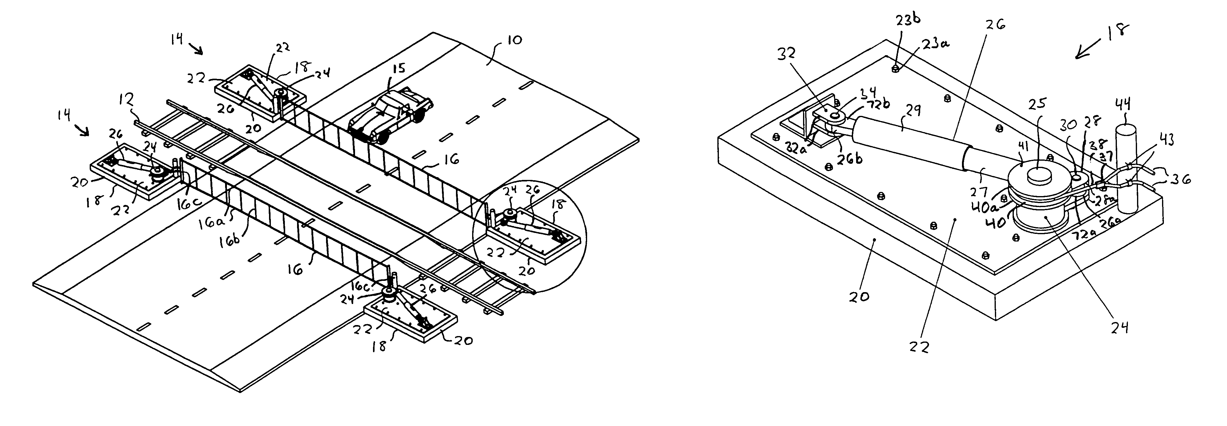
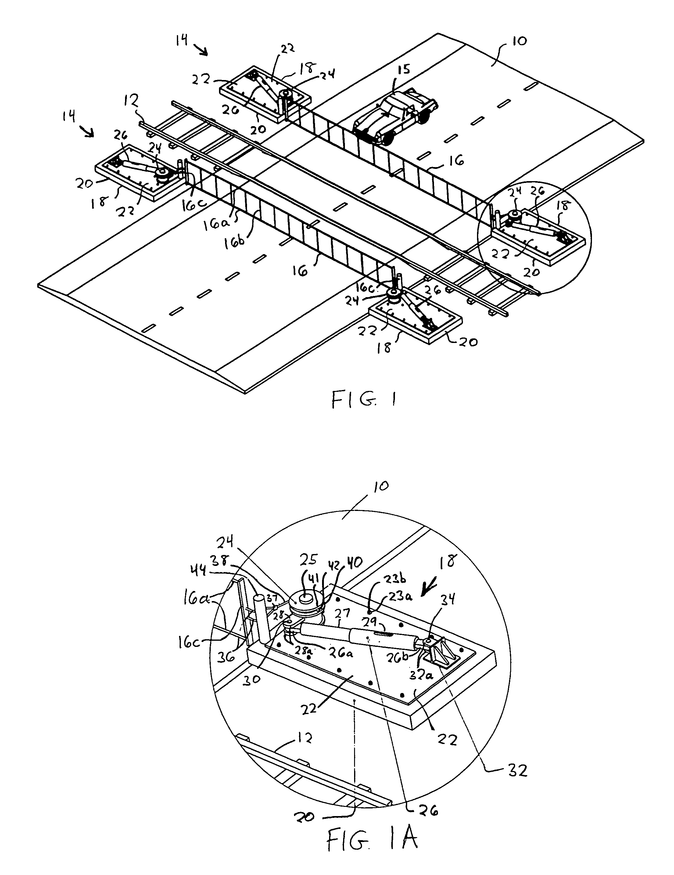
[0028]Referring to FIG. 1, a typical railroad crossing for a roadway 10 is shown having two vehicle barriers 14 on opposite sides of railroad tracks 12. Each vehicle barrier 14 has a vehicle capture net 16 stretched across roadway 10 between a pair of platforms 18. Each platform has a rotatable spool or drum 24 attached by cables to a different end of the net 16, and a shock absorber 26 pivotally mounted to spool 24. The platforms 18 are identical, and a pair of platforms coupled to the same net 16 are in a mirrored orientation with respect to each other, as illustrated in FIG. 1. One of platforms 18 is shown in more detail in FIGS. 1A and 3A-3D when no impact by a vehicle on net 16 is present. Each platform 18 has a concrete pad 20 and a plate 22 attached to the pad. The plate 22 may be of stainless steel and attached to pad 20 by nuts 23a threaded onto anchor stubs 23b extending from the pad 20 through holes in plate 22. Spool 24 is rotationally mounted on a fixed post 25 extendin...


PUM


Abstract

In order to stop a moving vehicle without injury to occupants, a vehicle barrier is provided having a pair of platforms disposed on opposite sides of a roadway, and a capture net extending across the roadway between the platforms. Each platform has a rotatably mounted spool attached to a different end of the net, and a dual acting extension-compression shock absorber pivotally mounted to the spool, such that when the force or energy of an impacting vehicle on the net is applied to the shock absorbers, via rotation of the spools. Rotation of spools operate the shock absorbers in compression, and if needed, in extension. In railroad crossing application, two of the vehicle barriers are provided on either side of the railroad tracks to prevent vehicles from crossing the railroad tracks.

Description

FIELD OF THE INVENTION[0001]The present invention relates to a vehicle barrier (and system and method) for absorbing energy of a moving vehicle in a captive net that stretches across a roadway, and particularly to a vehicle barrier in which the impact energy of the vehicle on the net is applied to shock absorbers via rotation of drums or spools coupled the ends of the net. Two of such vehicle barriers may be provided across a roadway on opposite sides of a railroad track to prevent vehicles from crossing the railroad track when a train is present. The invention may also be used in any other application to stop a moving vehicle, such as drawbridges, HOV traffic control, security gates, or crash cushion applications.BACKGROUND OF THE INVENTION[0002]The problem of vehicles improperly crossing railroad tracks is becoming more pronounced due to a rise in both the average speed of trains and in the number of vehicles on the roads. Traditional systems for preventing vehicles from crossing ...

Claims


Application Information

Patent Timeline
Patent Type & Authority Patents(United States)
IPC IPC(8): E01F15/00
CPCE01F13/12
Inventor METZGER, JOHN C.
Owner TAYLOR DEVICES
Why Eureka
Try Eureka