
Railway crossing structure

a crossing structure and railway technology, applied in the direction of tracks, superstructures, constructions, etc., can solve the problems of uneven crossing surface, less expense, and wear quite quickly

Inactive Publication Date: 2003-09-11
IHEC ACQUISITION
View PDF2 Cites 25 Cited by
  • Summary
  • Abstract
  • Description
  • Claims
  • Application Information

AI Technical Summary

Problems solved by technology

Construction of railroad tracks along streets has long presented the problem of how to provide long-lasting serviceability and track evenness with the road surface, while still giving needed access to the rails and supporting structures at lesser expense than has previously been possible.
Timber crossings, for example, wear quite quickly and soon present a rough crossing surface.
While asphalt wears better than timber, it is difficult to compact asphalt immediately adjacent to the rails.
In addition, it is difficult to prevent water from entering between the asphalt and the rails and when freezing occurs the water expands and causes deterioration of the asphalt.
Concrete wears better than asphalt and does not require mechanical compaction, however, freezing is a problem with this material also.
In addition, concrete grade crossings usually have metal edges which occasionally causes shorting to occur between the rails which can activate the crossing signs.
Raymond U.S. Pat. No. 4,793,545 discloses sealing insert assemblies which extend along the length of the rails of an embedded track, but which appear likely to be costly to construct and yet unable to provide access to the rail support structure for repair.
The disclosed structure, however, requires specially pre-cast panels which rest on the pads, making such structure undesirably expensive for use along a railway track embedded in a paved street.
The disclosed structure, however, requires the retainer form to be removed from atop the rail and filler bodies and the retainer strips are forced into the slot making the structure undesirably expensive and its installation time consuming.
Such filler structures are an added expense and, moreover, must not interfere with passage of railroad cars along the track.

Method used


Image

  • Railway crossing structure
  • Railway crossing structure
  • Railway crossing structure

Examples


Embodiment Construction

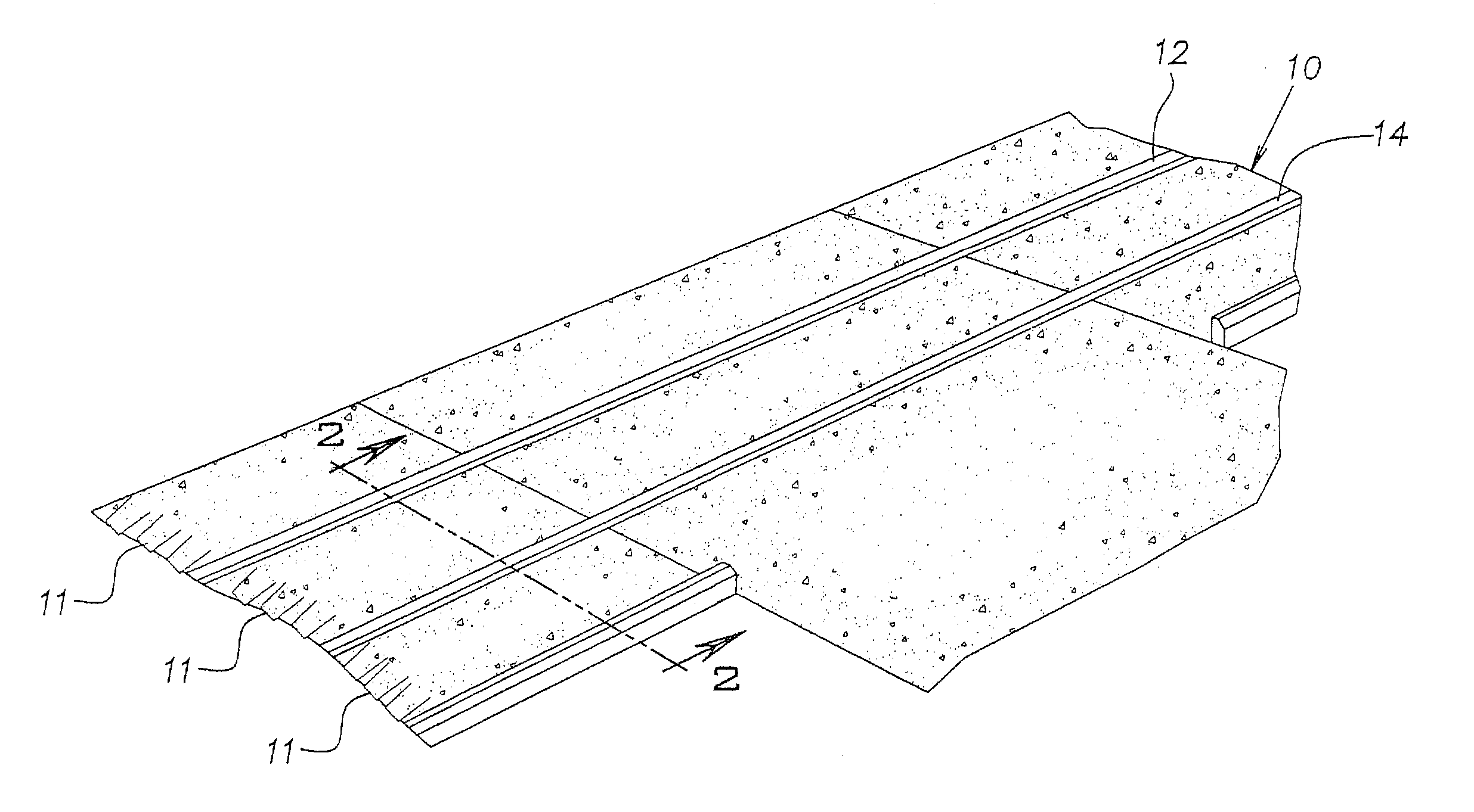
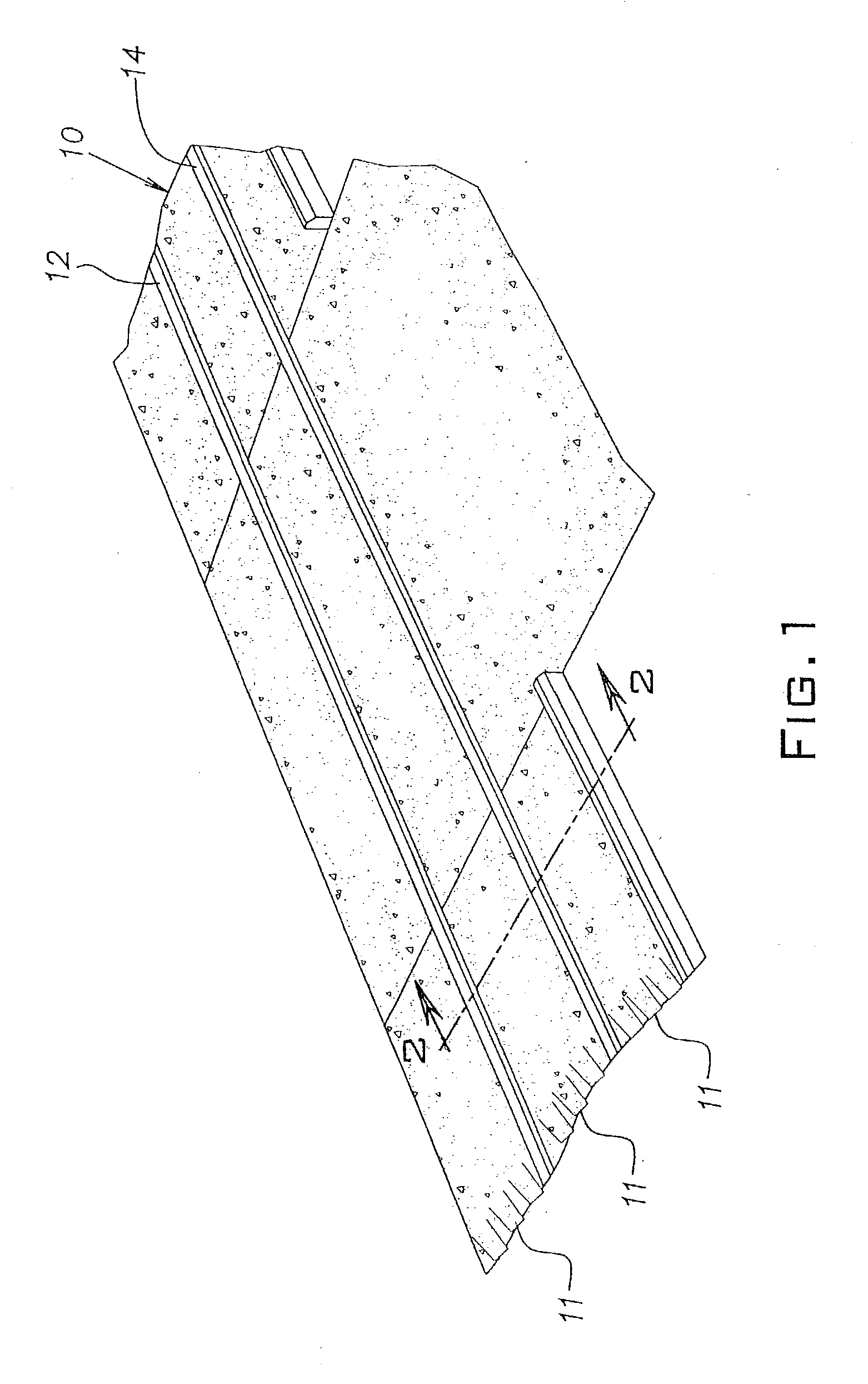
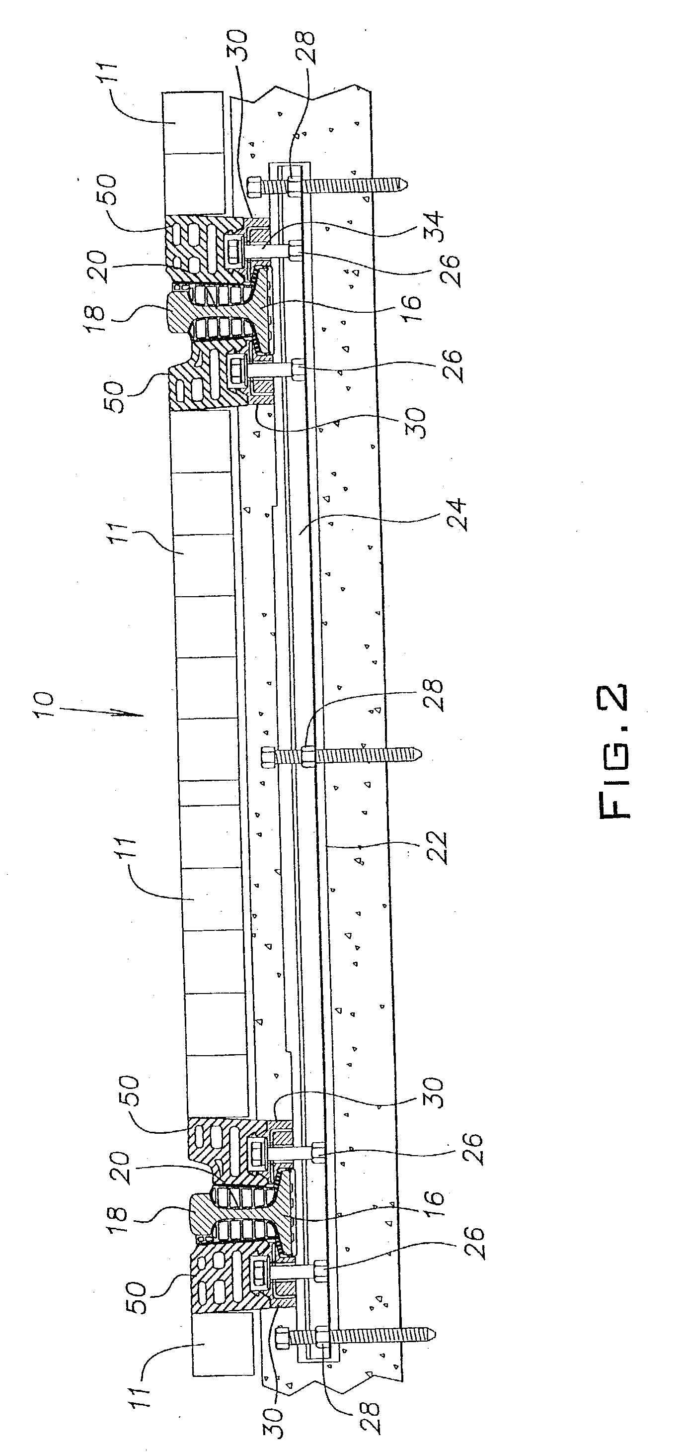
[0022] Referring now to the drawings wherein the showings are for purposes of illustrating an example embodiment of the invention only and not for limiting the same, FIGS. 1 and 2 show a railway track structure 10 that is serviceable and electrically insulates the rails from the surrounding ground surface.

[0023] More particularly, the railway structure includes a pair of spaced parallel rails 12, 14 each having a generally I-shaped cross-section, for example, a 115 RE type rail. Each rail includes a base portion 16 or rail flange, a head portion 18 and a web 20 integrally connecting the head and base portions. Paver blocks 11 define a finished grade but are incidental to the design. The finished grade could be any structural material or comprise a grass median strip in a so-called grass track application . The area currently filled in with the paver blocks 11 could be filled in with concrete or asphalt.

[0024] Typically, the base portion 16 of rail 12, 14 is operatively supported alo...


PUM


Abstract

An insulation system for an embedded track construction for a transit railway having spaced parallel railway rails includes a rail boot for substantially enclosing each of the rails along its length, rail clips extending on each side of each of the rails for securing the rails to supporting ties, and fillers extending on each side of each of the rails, frictionally engaging and removably mounting the rails to an associated one of said rail clips. The fillers cooperate to provide a coplanar roadway with said rails.

Description

[0001] This application claims the priority of U.S. Provisional Application No. 60 / 362,636, filed Mar. 8, 2002.[0002] 1. Field of the Invention[0003] The present invention relates to the art of railway track assemblies and more particularly, to an embedded railway track structure using elastomeric elements.[0004] 2. Description of the Related Art[0005] Construction of railroad tracks along streets has long presented the problem of how to provide long-lasting serviceability and track evenness with the road surface, while still giving needed access to the rails and supporting structures at lesser expense than has previously been possible.[0006] Where tracks are embedded in pavement it is necessary to have a gutter to contain each rail, yet is must also be possible to gain access to the rail, its supporting structures, and fasteners attaching the rail to the supporting structures, once the gutter has been sealed.[0007] Many highways and arterials which cross railroad tracks utilize ela...

Claims


Application Information

Patent Timeline
IPC IPC(8): E01B19/00E01C9/04
CPCE01C9/04E01B19/003
Inventor HOFSTETTER, DON R. SR.
Owner IHEC ACQUISITION
Learn More