
Endotracheal Tube Holder

Inactive Publication Date: 2008-08-28
PARA PRODS
View PDF59 Cites 28 Cited by
  • Summary
  • Abstract
  • Description
  • Claims
  • Application Information

AI Technical Summary

Benefits of technology

[0012]An alternate embodiment of the invention includes a curved section protruding from the bottom of the retaining base which functions as a bite block. The bite block prevents the patient from clamping his teeth down on the endotracheal tube and preventing oxygen from reaching the lungs.

Problems solved by technology

Unwanted movement could result in the loss of oxygen to the patient's lungs, and the loss of respiration, and possibly injury or death of the patient.

Method used


Image

  • Endotracheal Tube Holder
  • Endotracheal Tube Holder
  • Endotracheal Tube Holder

Examples


Embodiment Construction

[0029]While this invention is susceptible of embodiment in many different forms, there are shown in the drawings, and will be described herein in detail, specific embodiments thereof with the understanding that the present disclosure is to be considered as an exemplification of the principles of the invention, and is not intended to limit the invention to the specific embodiments illustrated.

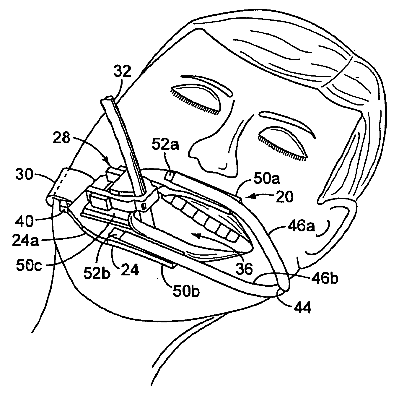
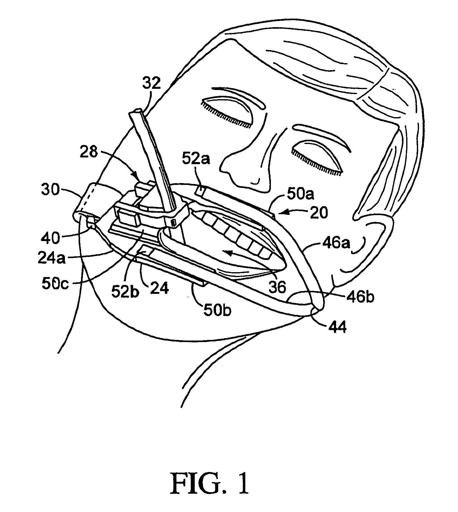
[0030]FIG. 1 illustrates the endotracheal tube holder 20 of the invention strapped to a patient. The holder 20 includes a base 24 and a tube-holding assembly 28. The base 24 is secured onto the patient by a strap 30. The tube-holding assembly 28 holds an endotracheal tube 32 which enters the patient's mouth 36 and is positioned in the trachea.

[0031]The strap 30 is threaded into a strap loop 40 formed on an end of the base 24 and secured upon itself to affix the strap 30 to the base 24. The strap is preferably a one-piece hook and loop (such as VELCRO) fabric material which can be separated into ...


PUM


Abstract

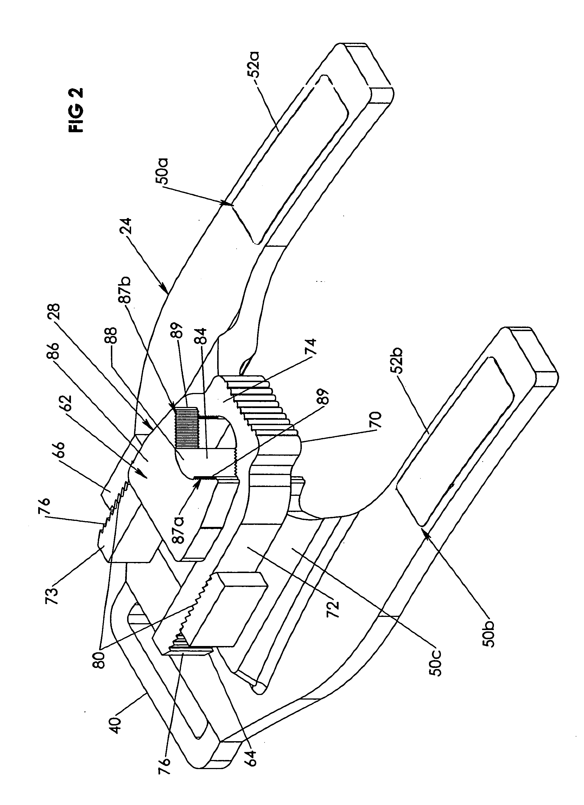
An endotracheal tube holder for restraining an endotracheal tube in a patient's mouth includes a base that is strapped to the patient's head. The base includes a tube-securing block and clip-securing blocks. A separate, U-shaped clip is engagable in ratchet fashion to the base between the tube-securing block and the clip restraining blocks to secure the endotracheal tube to the tube-securing block.

Description

TECHNICAL FIELD OF THE INVENTION[0001]The present invention relates generally to an endotracheal tube-holding apparatus and more particularly to an endotracheal tube holder in which an endotracheal tube is secured to be correctly position within the patient's mouth and trachea.BACKGROUND OF THE INVENTION[0002]An endotracheal tube holder is used on a patient for securing and holding in place an endotracheal tube. The endotracheal tube is a narrow, hollow tube which is inserted through a patient's mouth and into the trachea. The purpose of the tube is to provide oxygen to the lungs of the patient to support respiration.[0003]In use, a portion of the endotracheal tube is left to protrude from the patient's mouth so that a ventilation device can be attached to the end of the tube to provide forced or assisted ventilation to the patient. The endotracheal tube holder is placed on the patient's face, having an opening in registry with the patient's mouth. The tube is held in place by attac...

Claims


Application Information

Patent Timeline
IPC IPC(8): A61M16/00A61M16/04
CPCA61M16/0488A61M16/0493A61M16/0497A61B1/00154
Inventor FLORY, JAMES M.KAUTH, MARK A.CAMODECA, TIMOTHY F.
Owner PARA PRODS
Learn More