
Fixing device
- Summary
- Abstract
- Description
- Claims
- Application Information
AI Technical Summary
Benefits of technology
Problems solved by technology
Method used
Image

Examples
first embodiment
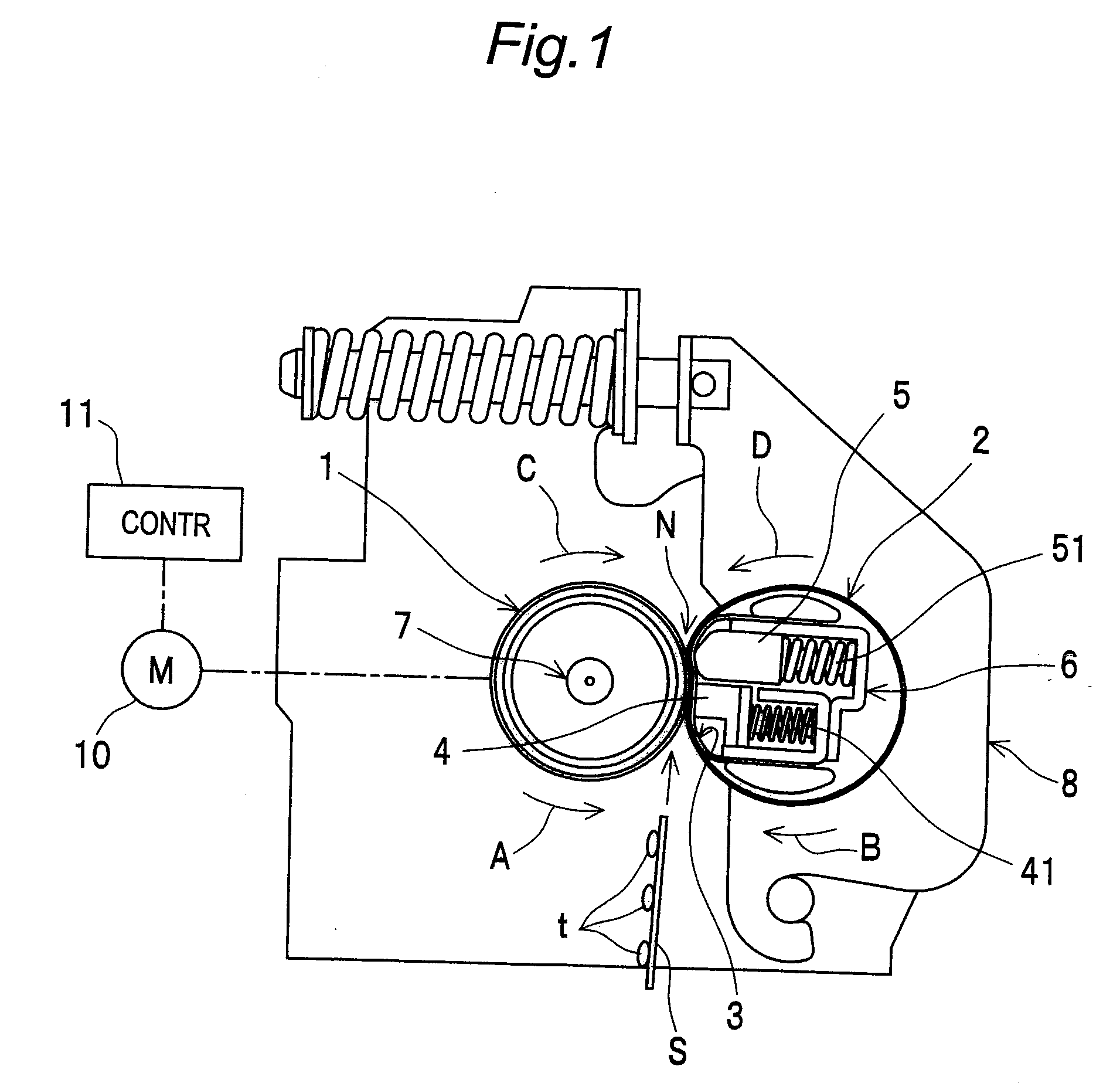
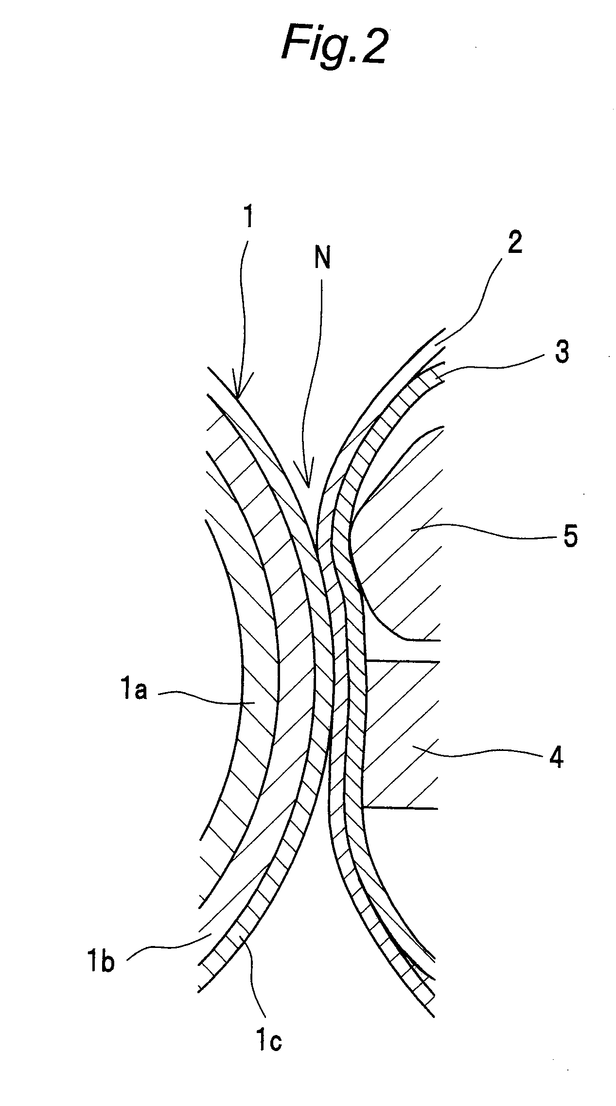
[0030]FIG. 1 shows a schematic structural view of a fixing device according to a first embodiment of the present invention. FIG. 2 shows an enlarged sectional view of a nip portion. The fixing device is used for an image forming apparatus such as a copying machine, a printer or a facsimile.
[0031]The fixing device has a heating roller 1 and an endless pressure belt 2. The heating roller 1 is served as a heating rotation unit. The endless pressure belt 2 is brought in external contact with the heating roller 1 and rotated to follow the rotation of the heating roller 1. A nip portion N is formed between the heating roller 1 and the pressure belt 2.
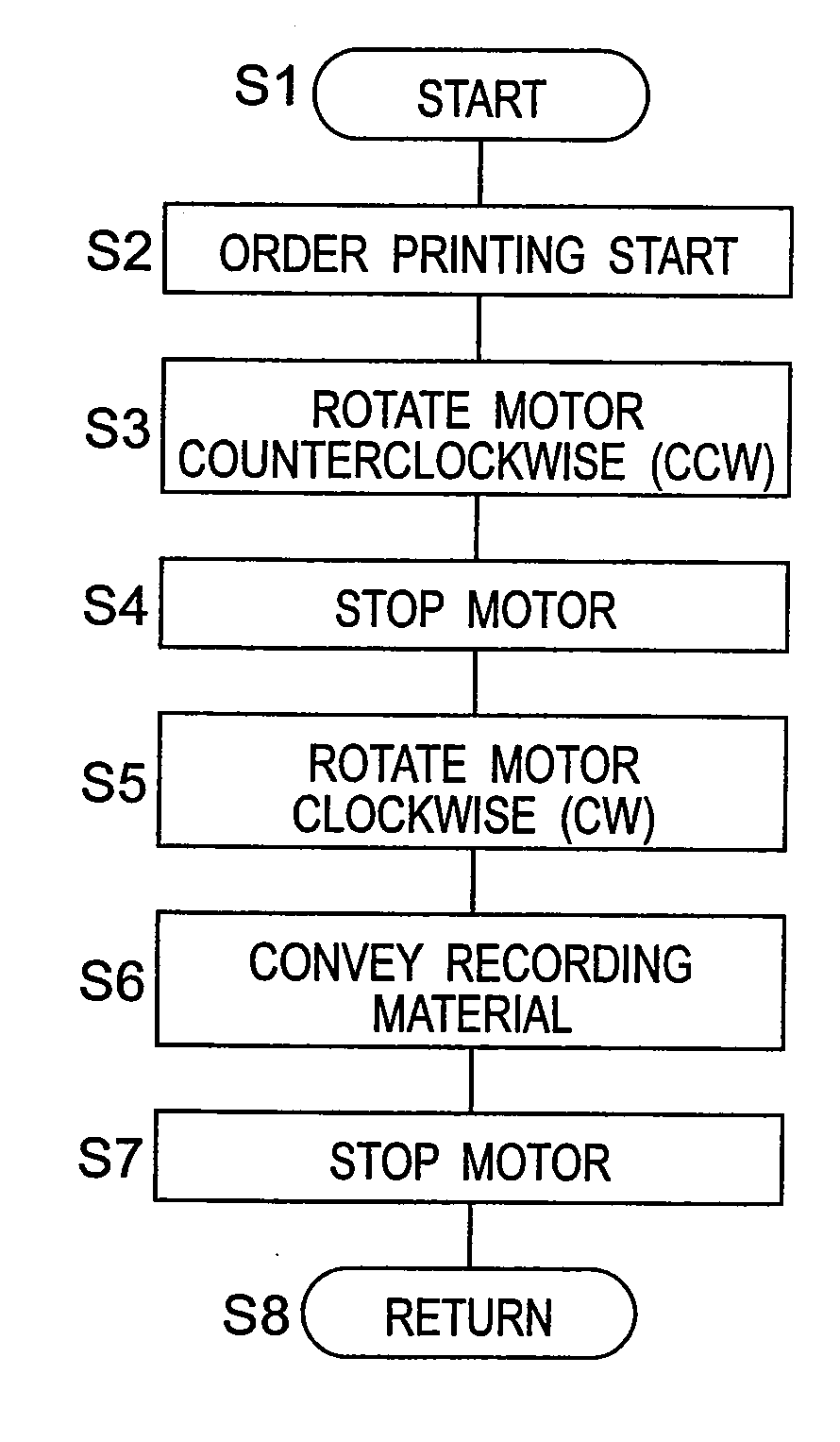
[0032]The heating roller 1 is heated by a halogen lamp 7 placed inside as a heat source, and the heating roller 1 is rotated by a motor 10 as a driving source. The motor 10 is controlled by a control unit 11.
[0033]Inside the pressure belt 2, a first pressurizing member 4 and a second pressurizing member 5 are arranged side by side in the rota...
second embodiment
[0065]FIG. 7 shows the fixing device according to a second embodiment of the present invention. The fixing device of the second embodiment is structurally different from the first embodiment (FIG. 1) in a point that the pressure contact force between the heating roller 1 and the pressure belt 2 can be switched from one stage to another stage. Since the other structures than the above are the same as those of the first embodiment, no description is provided therefor.
[0066]That is, in the present second embodiment, it is possible to switch over between a pressure contact state in a normal fixing mode as shown in FIG. 7 and a pressure contact state in an envelope fixing mode as shown in FIG. 8. In the normal fixing mode, a paper sheet such as a plain-paper or a thick paper, which does not easily wrinkle, is fixed as the recording material S. In the envelope fixing mode, a paper sheet such as an envelope, which easily wrinkles, is fixed as the recording material S. More specifically, th...
PUM
 Abstract
Description
Claims
Application Information