Orthogonal electrical connector with increased contact density

a technology of contact density and orthogonal connector, which is applied in the direction of electrical apparatus, connection, coupling device connection, etc., can solve the problems of limited contact density in orthogonal connectors and limitations of conventional orthogonal connectors

Inactive Publication Date: 2008-09-04
TE CONNECTIVITY CORP
View PDF12 Cites 68 Cited by
  • Summary
  • Abstract
  • Description
  • Claims
  • Application Information

AI Technical Summary

Benefits of technology

[0006]In another aspect, an electrical connector assembly including a pair of connectors configured to be electrically connected to one another from opposite sides of a circuit board is provided. The electrical connector assembly includes first and second connector housings. Each connector housing has a mating face and a mounting face. The mounting faces are configured to be electrically connected to one another from opposite sides of the circuit board approximately in line with one another along a longitudinal axis such that the connector housings are angularly offset ninety degrees about the longitudinal axis with respect to one another. Signal and ground co...

Problems solved by technology

However, conventional orthogonal connectors have experienced certain limitations.
Heretofore, ...

Method used


Image

  • Orthogonal electrical connector with increased contact density
  • Orthogonal electrical connector with increased contact density
  • Orthogonal electrical connector with increased contact density

Examples


Embodiment Construction

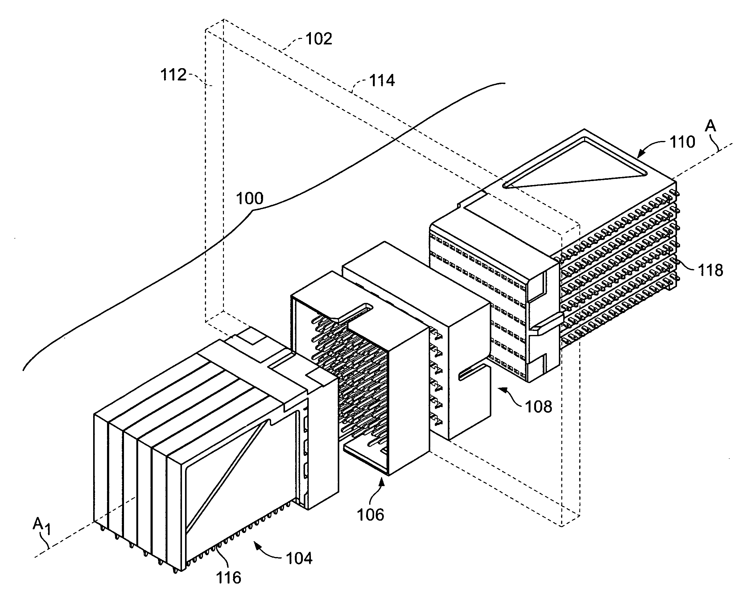
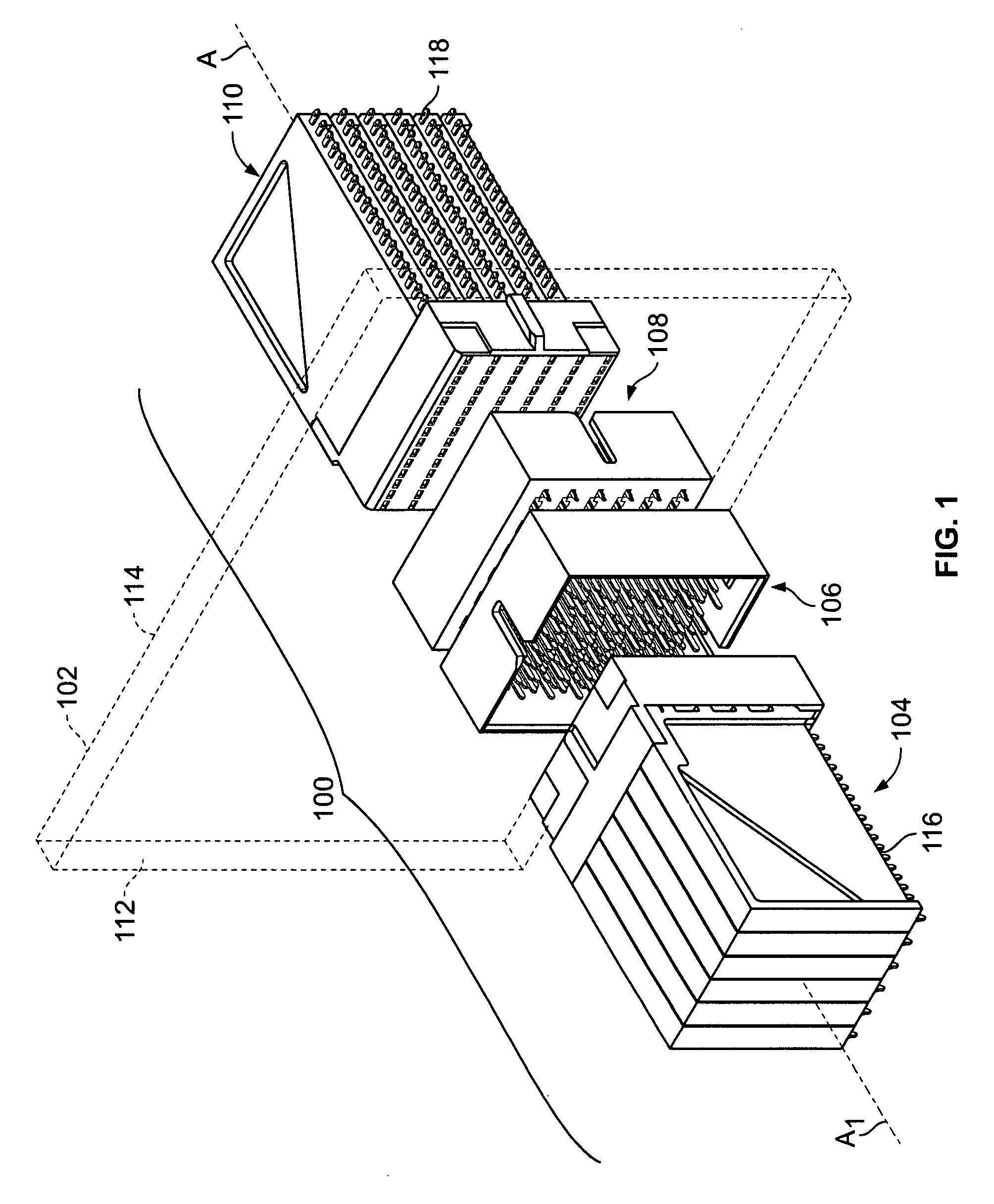
[0018]FIG. 1 is a perspective view of an orthogonal connector assembly 100 formed in accordance with an embodiment of the present invention. The connector assembly 100 is mounted on a midplane circuit board 102, which is shown in phantom lines for clarity. The connector assembly 100 includes a receptacle connector 104, a header connector 106, a header connector 108, and a receptacle connector 110. The header and receptacle connectors 106 and 104, respectively, are mounted on a first side 112 of the midplane 102 and connect through the midplane 102 to the header and receptacle connectors 108 and 110, respectively, which are mounted on a second side 114 of the midplane 102.

[0019]The receptacle connector 104 includes a daughter card interface 116. By way of example only, the receptacle connector 104 may be mounted on a line card (not shown) at the interface 116. Similarly, the receptacle connector 110 includes a daughter card interface 118 and, by way of example only, the receptacle co...


PUM


Abstract

An electrical connector includes a housing that holds signal contacts which are associated as signal contact pairs. The housing has a mounting face and the signal contact pairs are aligned in rows along the mounting face. Each of the rows includes multiple signal contact pairs. Each of the signal contact pairs includes two of the signal contacts aligned on a respective axis. The axes of the signal contact pairs within each row are aligned in a common direction, and the axes of the signal contact pairs in adjacent rows are aligned in respective different directions.

Description

BACKGROUND OF THE INVENTION[0001]The invention relates generally to electrical connectors and, more particularly, to a connector that may be used in an orthogonal relationship with an identical connector on both sides of a midplane.[0002]Some electrical systems, such as network switches and computer servers with switching capability, include connectors that are oriented orthogonally on opposite sides of a midplane in a cross connect application. Switch cards may be connected on one side of the midplane and line cards may be connected on the other side of the midplane. The line card and switch card are joined through connectors that are sometimes mounted on the midplane in an orthogonal relation to one another. The connectors include patterns of signal and ground contacts that extend through a pattern of vias in the midplane.[0003]However, conventional orthogonal connectors have experienced certain limitations. For example, it is desirable to increase the density of the signal and gr...

Claims


Application Information

Patent Timeline
IPC IPC(8): H01R13/514H01R12/71
CPCH01R13/514H01R13/6477H01R13/6471H01R12/724
Inventor ROTHERMEL, BRENT RYANFOGG, MICHAEL WARREN
Owner TE CONNECTIVITY CORP
Why Eureka
Try Eureka