Electrosurgical tissue removal with a selectively insulated electrode

a selective isolation, electrode technology, applied in the field of electrosurgical devices, can solve the problems of obstructing the physician's view, dangerous blood loss levels, nausea, etc., and achieve the effect of increasing current density and reducing energy loss

a selective isolation, electrode technology, applied in the field of electrosurgical devices, can solve the problems of obstructing the physician's view, dangerous blood loss levels, nausea, etc., and achieve the effect of increasing current density and reducing energy loss

US20080221567A1Inactive Publication Date: 2008-09-11BOSTON SCI SCIMED INC

Image

  • Electrosurgical tissue removal with a selectively insulated electrode
  • Electrosurgical tissue removal with a selectively insulated electrode
  • Electrosurgical tissue removal with a selectively insulated electrode

Examples


Embodiment Construction

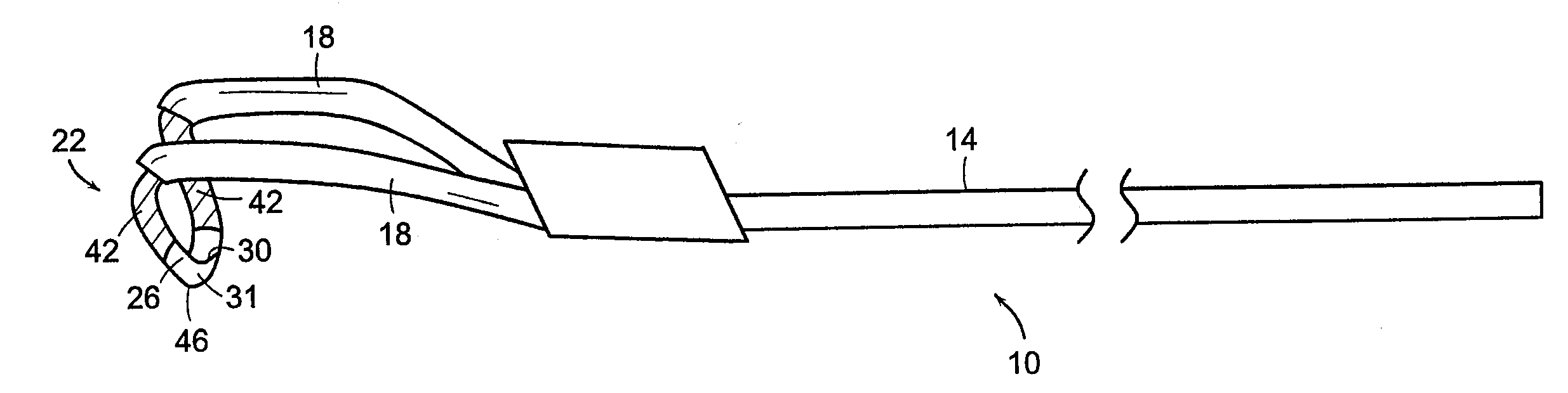
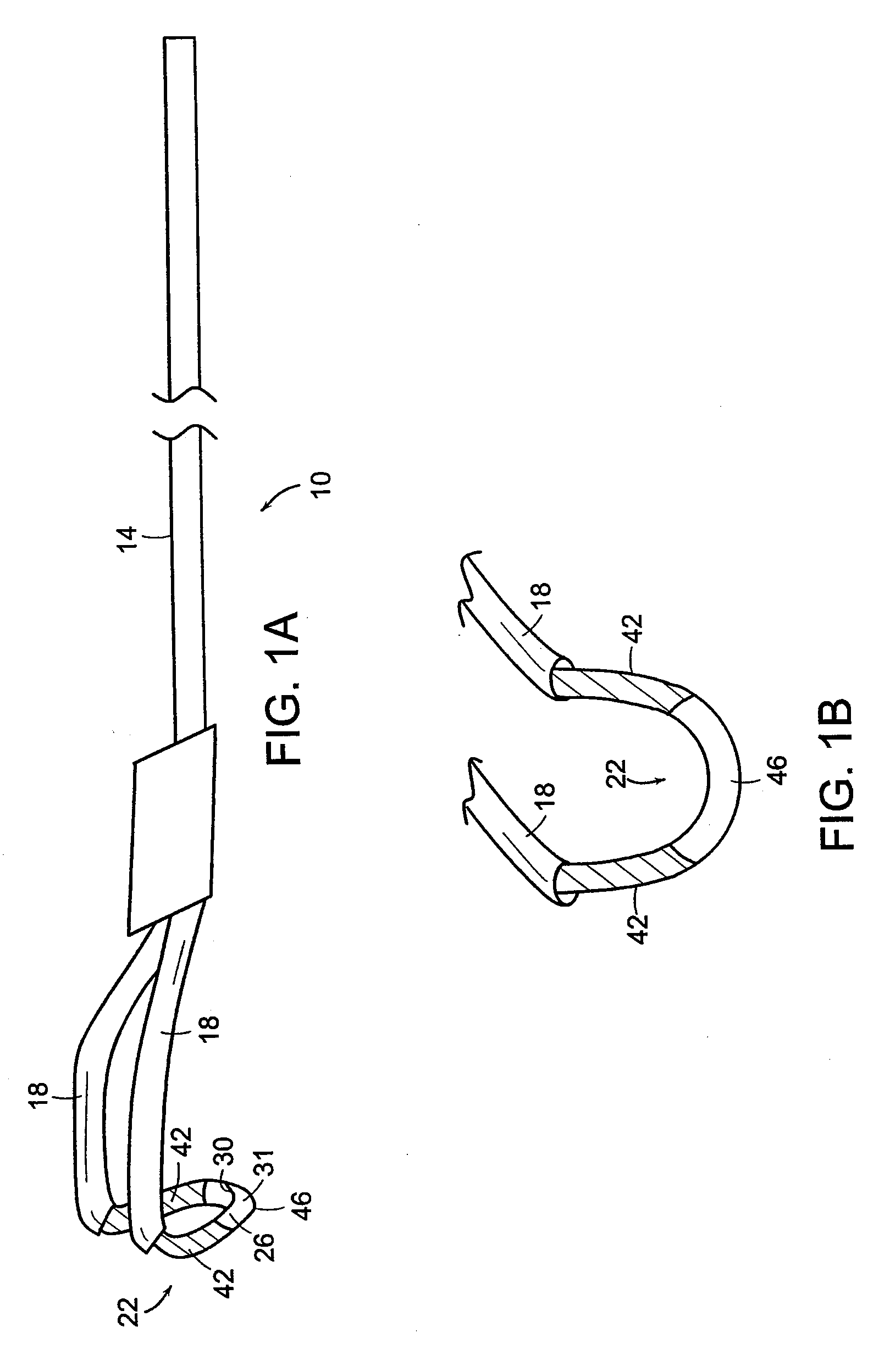
[0036]Referring to FIGS. 1a and 1b, a device 10 includes an elongated body 14, a pair of arms 18 extending from a distal end of the elongated body 14, and a broad loop electrode 22 connecting the pair of arms 18. U.S. Pat. No. 5,569,244 incorporated herein by reference describes the structure of the broad loop electrode 22. The broad loop electrode 22 is capable of both resecting and coagulating tissue. The pair of arms 18 comprises an electrical lead and an insulative sheath contains the leads. The proximal end of the elongated body 14 is adapted to be coupled to an energy source (not shown). Suitable conductive materials for forming the broad loop electrode 22, include, for example, stainless steel, tungsten, titanium, aluminum, brass, silver alloy, copper alloy, as well as other materials exhibiting conductive properties. The broad loop electrode 22 defines a pair of end sections 42 and a base section 46. Each end section 42 is coupled to an arm 18 and can comprise the conductive...


PUM

PropertyMeasurementUnit
thicknessaaaaaaaaaa
thicknessaaaaaaaaaa
thicknessaaaaaaaaaa

Abstract

An electrosurgical device includes an elongated body including a proximal end and a distal end and defining a longitudinal axis, at least one arm coupled to the distal end of the elongated body and an electrode coupled to at least one arm. The electrode includes an upper surface and a lower surface. The lower surface is substantially convex and defines a radius of curvature relative to an axis substantially perpendicular to the longitudinal axis.

Description

CROSS-REFERENCE TO RELATED APPLICATION [0001]This is a continuation-in-part of U.S. patent application Ser. No. 08 / 940,665 filed Sep. 30, 1997, the entirety of which is incorporated herein by reference.TECHNICAL FIELD [0002]This invention relates to electrosurgical devices, and more particularly to improved electrosurgical devices having selectively insulated portions for use in procedures such as resection, incision, ablation, and / or coagulation.BACKGROUND INFORMATION [0003]There are many medical procedures in which tissue is removed for diagnostic or therapeutic reasons. For example, transurethral resection of the prostate (TURP) is performed to treat benign or cancerous prostatic hyperplasia, which blocks the urethra. Transurethral resection may also be performed in the bladder (TURB). In a transurethral resection procedure, a resection electrode is inserted into the urethra of a patient through a resectoscope. An electric current applied through the electrode heats the prostate ...

Claims


Application Information

Patent Timeline
11 Sep 2008
Publication
US20080221567A1
IPC
A61B18/14
CPC
A61B18/042; A61B2218/007; A61B18/149; A61B2017/0088; A61B2018/00083; A61B2018/00107; A61B2018/00136; A61B2018/00547
Inventors
SIXTO, ROBERT; LENNOX, CHARLES D.