
Three-Piece Grip Safety

a three-piece, grip technology, applied in the field of handgun grip safety, can solve the problems of design, design, and unavoidable pressure upward on the underside of the beavertail portion, and achieve the effects of improving the safety of the grip, and increasing the positive interaction

Inactive Publication Date: 2008-09-18
CHRISTIANSEN NED F
View PDF1 Cites 10 Cited by
  • Summary
  • Abstract
  • Description
  • Claims
  • Application Information

AI Technical Summary

Benefits of technology

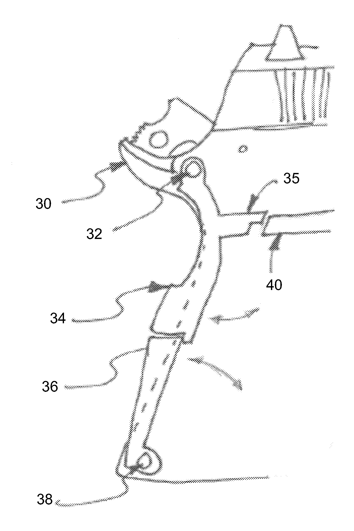
[0008]In view of the foregoing disadvantages inherent in the known types of grip safeties, this invention provides an improved two-piece grip safety. To accomplish these objectives, the improved grip safety comprises a fixedly attached body with a secondary pivoting member. The pivoting member is connected to a blocking arm which protrudes into the weapon and blocks the trigger bow. Towards the bottom of the pivoting member is a broad thick pressure plate to increase positive interaction between the pivoting member and a user's hand. The pivoting member likewise interacts with a tertiary pivoting lower member, which can bias the secondary pivoting member in the disengaged position.

Problems solved by technology

The result was that many shooters complained that full disengagement of the grip safety was difficult to obtain, resulting in the pistol not firing.
Other shooters fear this solution as a potential legal liability.
Pressure upward on the underside of the beavertail portion is counterproductive but unavoidable
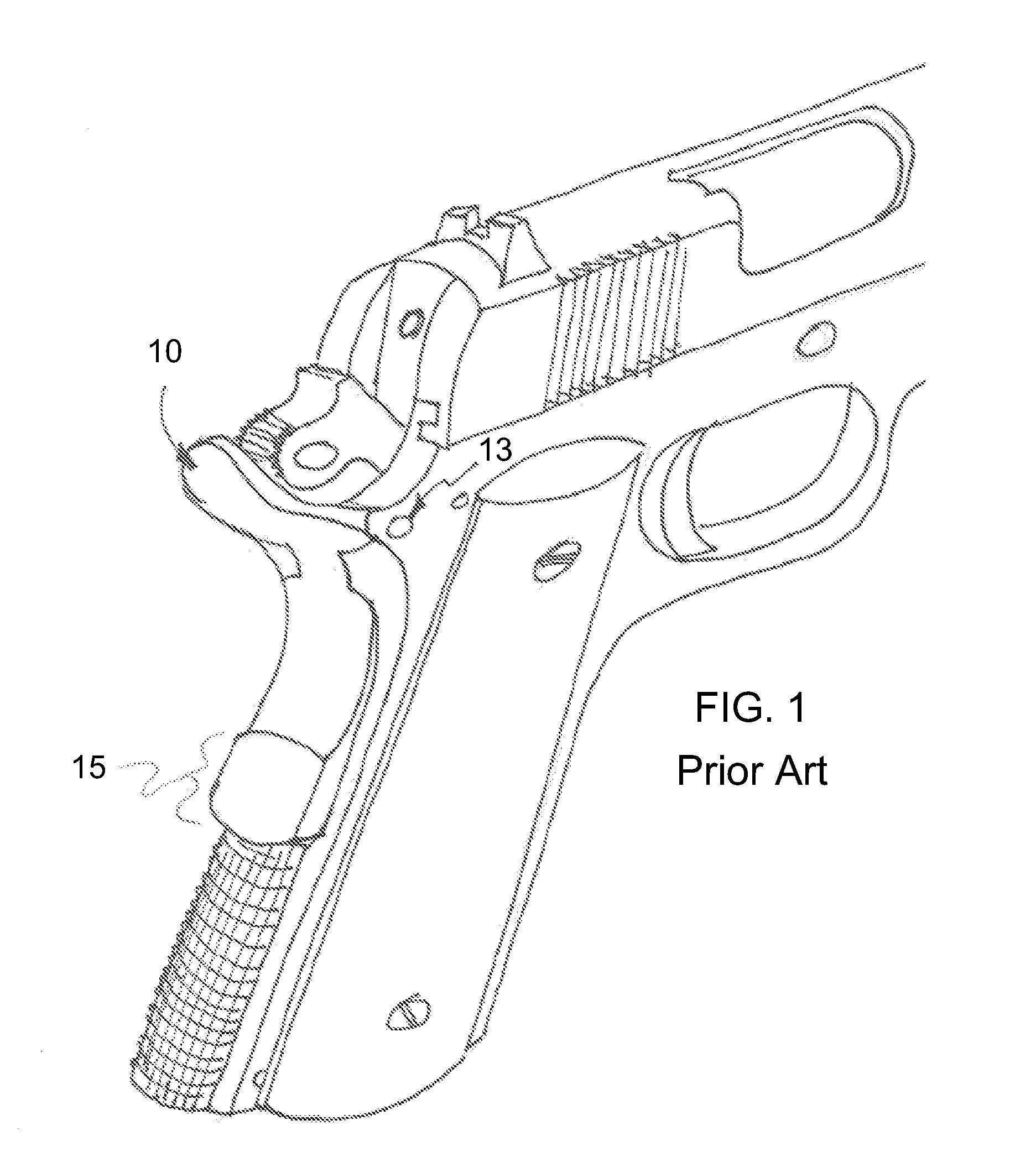
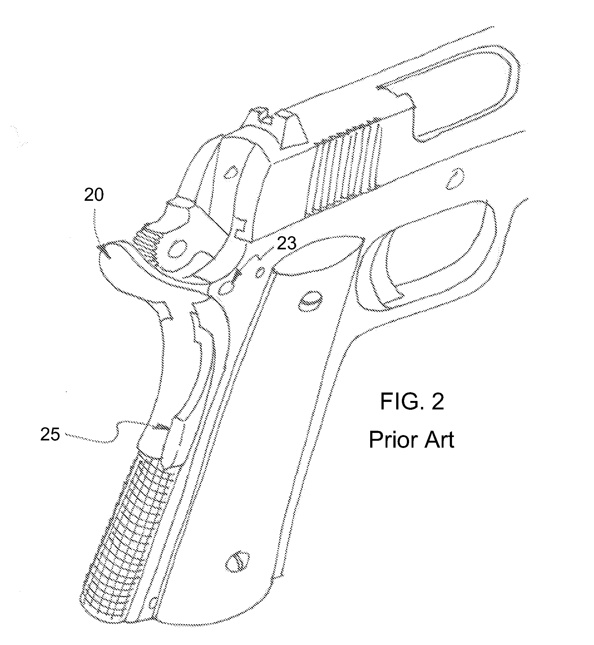
This design is, however, susceptible to accidental disengagement as the pivoting member is free to pivot about the pivot point 23 without hinderance.

Method used


Image

  • Three-Piece Grip Safety
  • Three-Piece Grip Safety
  • Three-Piece Grip Safety

Examples


Embodiment Construction

[0017]With reference now to the drawings, the preferred embodiment of the two-piece grip safety is herein described. It should be noted that the articles “a”, “an”, and “the”, as used in this specification, include plural referents unless the content clearly dictates otherwise.

[0018]With reference to FIGS. 3 and 4, the grip safety comprises a fixed main body 30, ideally of the beavertail style, and an adjacent pivoting member 34 mounted upon an upper pivot point 32. Pivoting member is generally located on the right hand side of the main body 30, though appropriate configurations of weapons would allow a left hand side mounting. Pivoting member 34 may also have an expended region or pad to further increase hand contact and depressive action. Extending into the firearm from the pivoting member 34 is a blocking arm 35 which engages trigger bow 40 and prevents firing of the weapon. Pivoting member also interfaces with pivoting base member 36 hinged on lower pivot point 38. These two mem...


PUM


Abstract

The present invention is an improved multiple piece grip safety for handguns. The safety comprises a fixed main body and two interfacing pivoting members, pivoting about the top and bottom of the grip respectively. The two interfacing pivoting members counteract each other to prevent accidental disengagement of the safety while also providing a more efficient purposeful disengagement.

Description

CROSS-REFERENCES TO OTHER APPLICATIONS[0001]This application claims priority on prior filed U.S. provisional application No. 60 / 895,301, filed Mar. 16, 2007, and incorporates the prior Application herein in its entirety.FIELD OF THE INVENTION[0002]The present invention relates to the field of firearms and more particularly relates to a grip safety for handguns which is structured in two pieces.BACKGROUND OF THE INVENTION[0003]The grip safety of a pistol is intended to prevent the pistol from firing until a proper firing grasp depresses it forward, pivoting on a pin. This action pivots the body of the grip safety inward. An integral blocking arm, which protrudes forward from the grip safety's main body and into the interior of the pistol, pivots upward as the grip safety is depressed inward. This upward motion of the arm removes it from the path of the trigger bow, allowing the trigger to be pulled and thus the pistol to be fired.[0004]The most common design for a grip safety is call...

Claims


Application Information

Patent Timeline
Patent Type & Authority Applications(United States)
IPC IPC(8): F41A17/22
CPCF41A17/22
Inventor CHRISTIANSEN, NED F.
Owner CHRISTIANSEN NED F
Learn More