

Variable size trocar
a trocar and variable-size technology, applied in the field of variable-size trocars, can solve problems such as tightness of tissue and musculatur
- Summary
- Abstract
- Description
- Claims
- Application Information
AI Technical Summary
Benefits of technology
Problems solved by technology
Method used
Image

Examples
Embodiment Construction
)
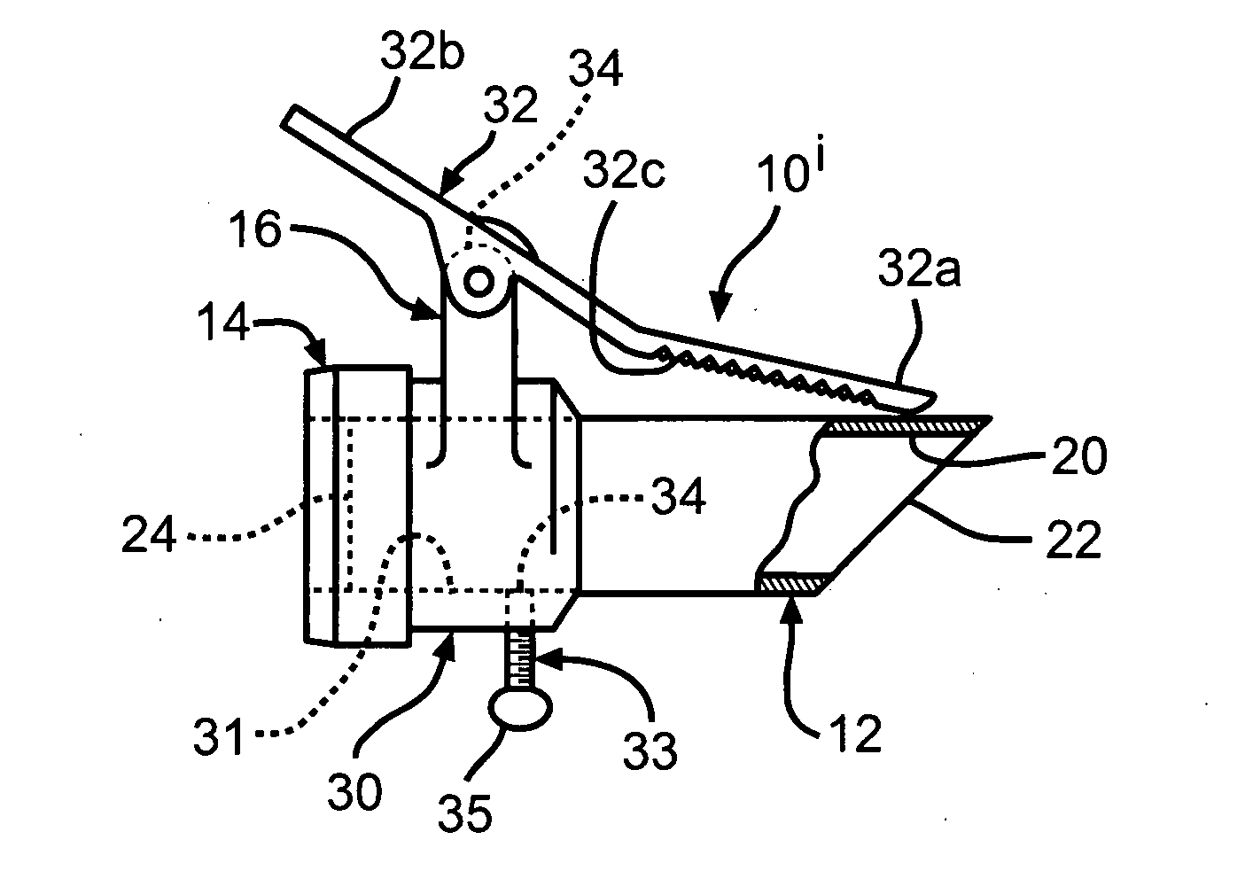
[0024]FIG. 1 is a side elevation showing one embodiment of a trocar 10i. The trocar 10i includes a guide tube 12 and a securing member 16.
[0025]The guide tube 12 defines an opening 20 for receiving a surgical tool or instrument. In the embodiment shown, for ease of illustration, the guide tube 12 will be generally illustrated as having a circular cross-sectional shape, but it should be understood that the guide tube can have other suitable shapes such as, for example, elliptical, oval, or any shape that will accommodate the clinician's instruments.
[0026]The guide tube 12 has a distal end 22 and a proximal end 24. In the embodiment shown, the distal end 22 has an angled shape to facilitate insertion of the distal end 22 into an open wound in the patient. While the embodiment shown illustrates the distal end 22 as being at an angle of about 45° with respect to a longitudinal axis defined by the guide tube 12, the angle can be at an angle other than 45°.
[0027]There is no special limit...
PUM
 Abstract
Description
Claims
Application Information