Sealed and cooled enclosure with voltage isolation

Inactive Publication Date: 2008-10-02
E2V TECH (UK) LTD
View PDF6 Cites 0 Cited by
  • Summary
  • Abstract
  • Description
  • Claims
  • Application Information

AI Technical Summary

Benefits of technology

[0007]According to a first aspect of the invention, there is provided a an enclosure for electrical apparatus comprising sealable outlet means for partially evacuating the enclosure and sealable inlet means for partially filling the enclosure with a liquid having a vapour pressure at operating temperatures of the apparatus suitable for a vapour from the liquid to enhance electrical isolation of the electrical apparatus and for the vapour to provide convective cooling of the electrical apparatus.
[0008]Advantageously, a vapour of the liquid provides a voltage hold-off sufficiently high for operating voltages of the electrical apparatus and has a relative permittivity sufficiently low to prevent stray capacitance due to the vapour above a predetermined limit.

Problems solved by technology

While this enhances both cooling and voltage hold off capabilities of electrical equipment within the enclosure, filling the enclosure with liquid significantly increases a weight of a system and requires means to accommodate expansion of the liquid.
This may restrict usable locations or positions of the assembly.
Many otherwise suitable liquids have a high dielectric constant and this significantly raises stray capacitance, which can be undesirable in, for example, high voltage Switched Mode Power Supply (SMPS) applications.
Moreover, some otherwise suitable liquids are very expensive and this additional cost can have significant adverse implications on a cost of the complete system.

Method used


Image

  • Sealed and cooled enclosure with voltage isolation
  • Sealed and cooled enclosure with voltage isolation
  • Sealed and cooled enclosure with voltage isolation

Examples


Embodiment Construction

[0034]Throughout the description, identical reference numerals are used to identify like parts.

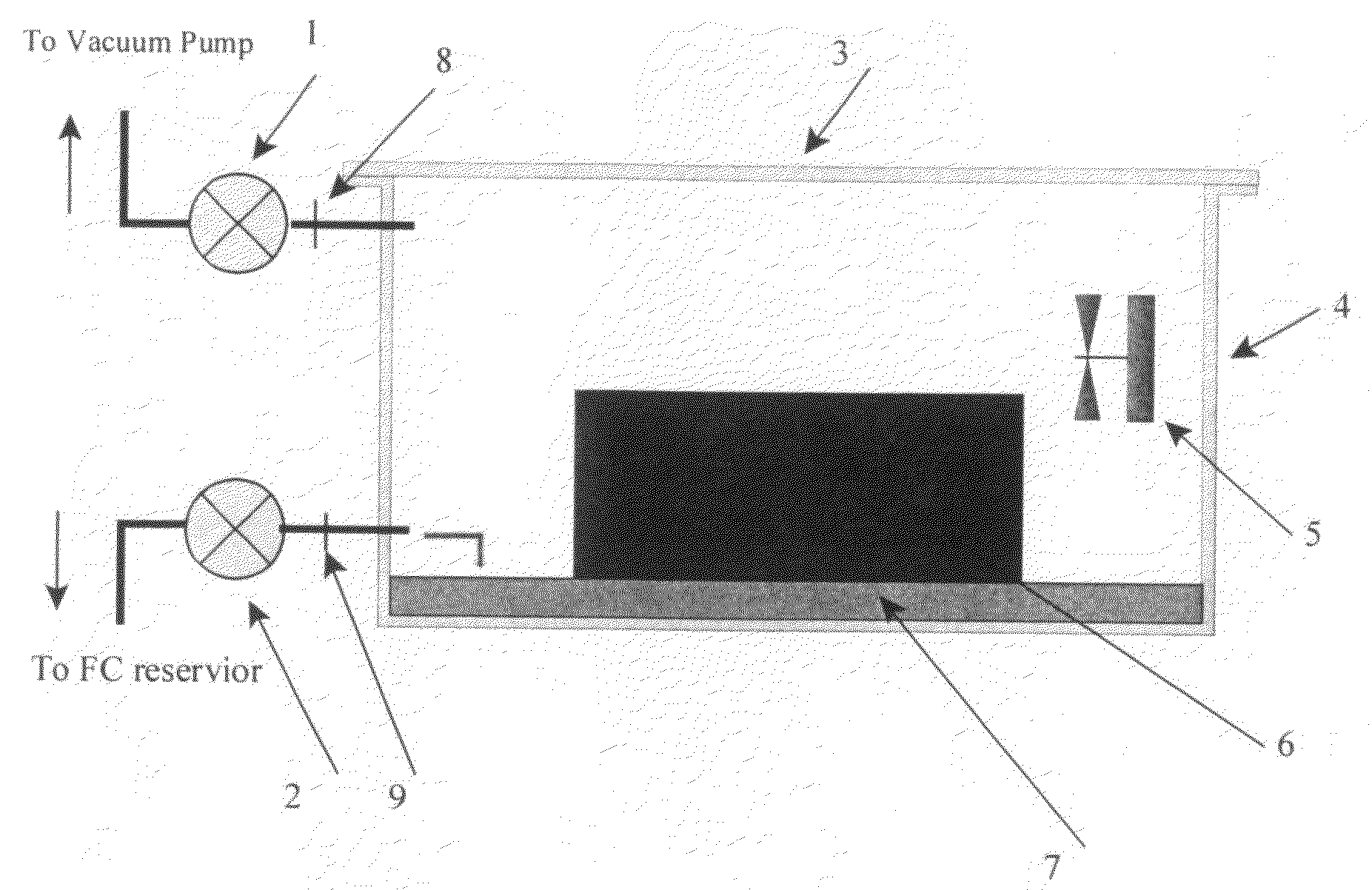
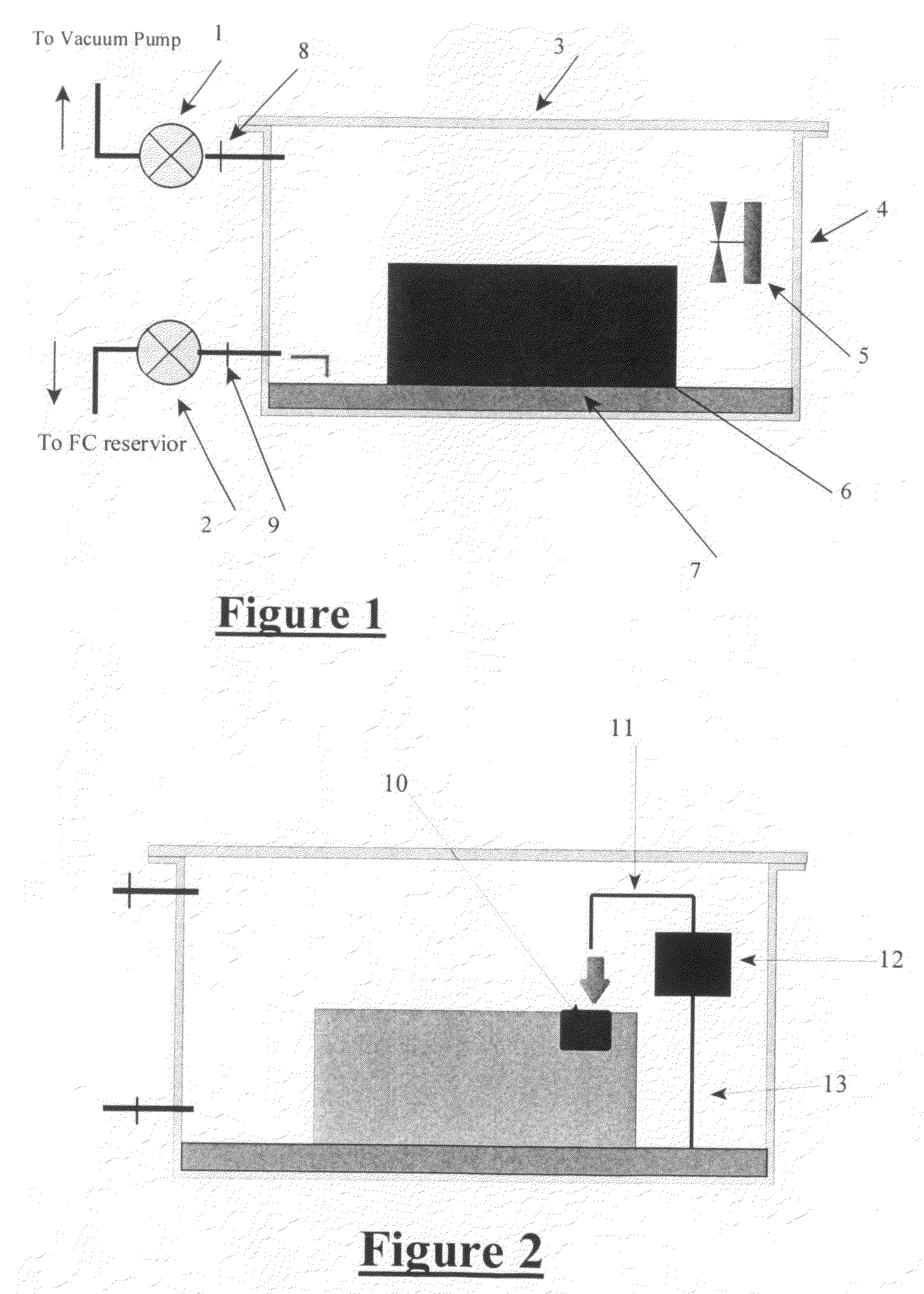
[0035]Referring to FIG. 1, a high voltage electronics system 6, with any other required additional components, is located in an enclosure 4 having a hermetically sealable closure or lid 3 closing an opening in the enclosure. In one embodiment the high voltage electronics system includes circuits working in a range of 1,000 to 50,000 volts. The enclosure is provided with an outlet pipe 8 and outlet valve 1 to which a vacuum pumping system is connectable. The enclosure is further provided with an inlet pipe 9 and inlet valve 2 connectable to an external liquid fluorocarbon reservoir. The enclosure is further provided with an internal fan 5.

[0036]Referring also to FIG. 4, prior to use the electronics system is located 41 in the enclosure and the enclosure lid sealed closed 42 in any suitable known manner. The enclosure and assembly are baked 43 at a temperature suitable to dry the electronics...


PUM


Abstract

An enclosure 4 for electrical apparatus 6 has a sealable outlet 8 for partially evacuating the enclosure and a sealable inlet 9 for partially filling the enclosure with a liquid 7 having a vapour pressure at operating temperatures of the apparatus suitable to enhance electrical isolation of the electrical apparatus and suitable to provide convective cooling of the electrical apparatus. The vapour preferably provides a voltage hold-off sufficiently high for operating voltages of the electrical apparatus and has a relative permittivity sufficiently low to prevent stray capacitance in the electrical apparatus above a predetermined limit.

Description

CROSS-REFERENCE TO RELATED APPLICATIONS[0001]This application claims priority from UK patent application GB 0706196.3 filed Mar. 29, 2007.FIELD OF THE INVENTION[0002]This invention relates to a sealed and cooled enclosure with voltage isolation.BACKGROUND OF THE INVENTION[0003]It is well known that sealing an electronics assembly or system in an enclosure to exclude an ambient environment can improve reliability of the system. Effects on the system of damp, particles, pollution, and changes in ambient atmospheric pressure and density may be substantially eliminated. It is known that for high voltage systems protection from these undesirable environments is even more important and use of a sealed enclosure to protect a high voltage assembly or system is well known.[0004]Known methods, such as described in WO 2005 / 081401, may also be used to extract heat from an assembly in an enclosure, for example, by circulation of air between an internal heat exchanger and an external heat exchang...

Claims


Application Information

Patent Timeline
IPC IPC(8): H05K7/20
CPCH01B3/56H05K5/06
Inventor RICHARDSON, ROBERT
Owner E2V TECH (UK) LTD
Why Eureka
Try Eureka