Display Device

Inactive Publication Date: 2008-10-23
KONINKLIJKE PHILIPS ELECTRONICS NV
View PDF7 Cites 17 Cited by
  • Summary
  • Abstract
  • Description
  • Claims
  • Application Information

AI Technical Summary

Benefits of technology

[0004]An object of the present invention is therefore to

Problems solved by technology

A disadvantage with such a display is the high speed requirements imposed on the LCD panel in order to ac

Method used


Image

  • Display Device
  • Display Device
  • Display Device

Examples


first embodiment

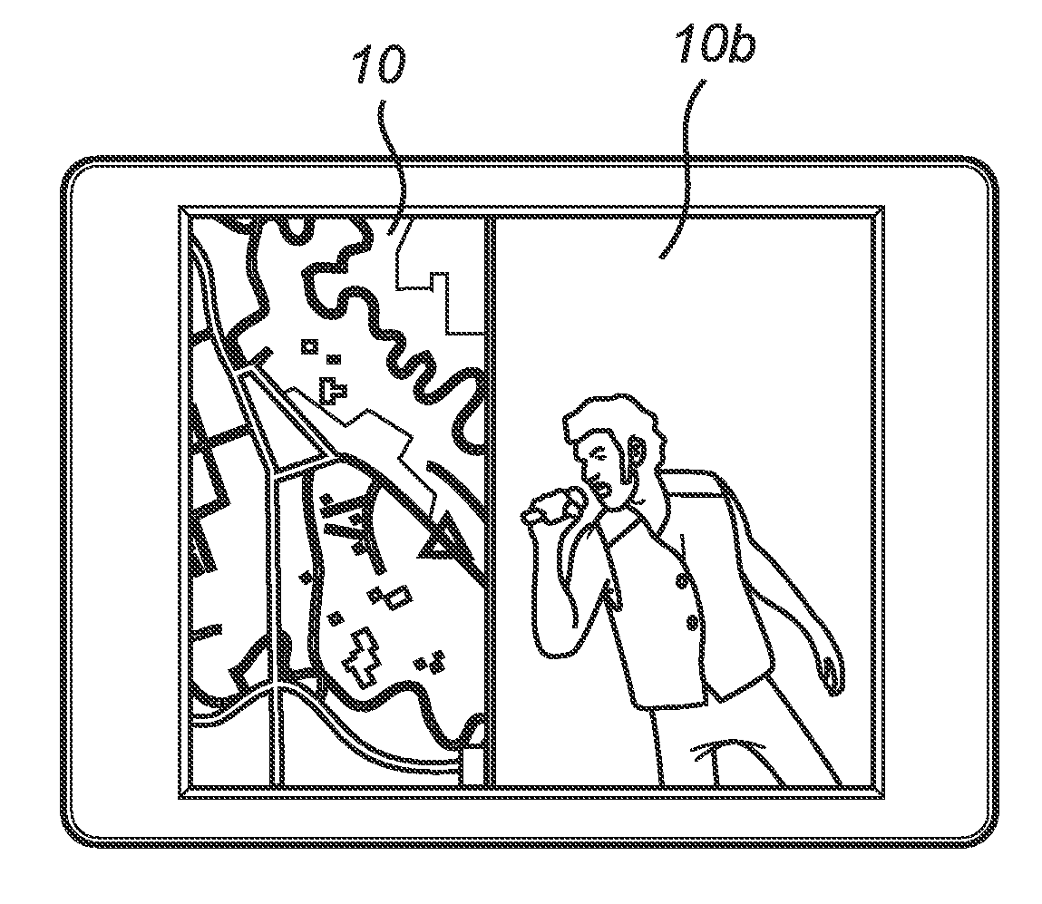
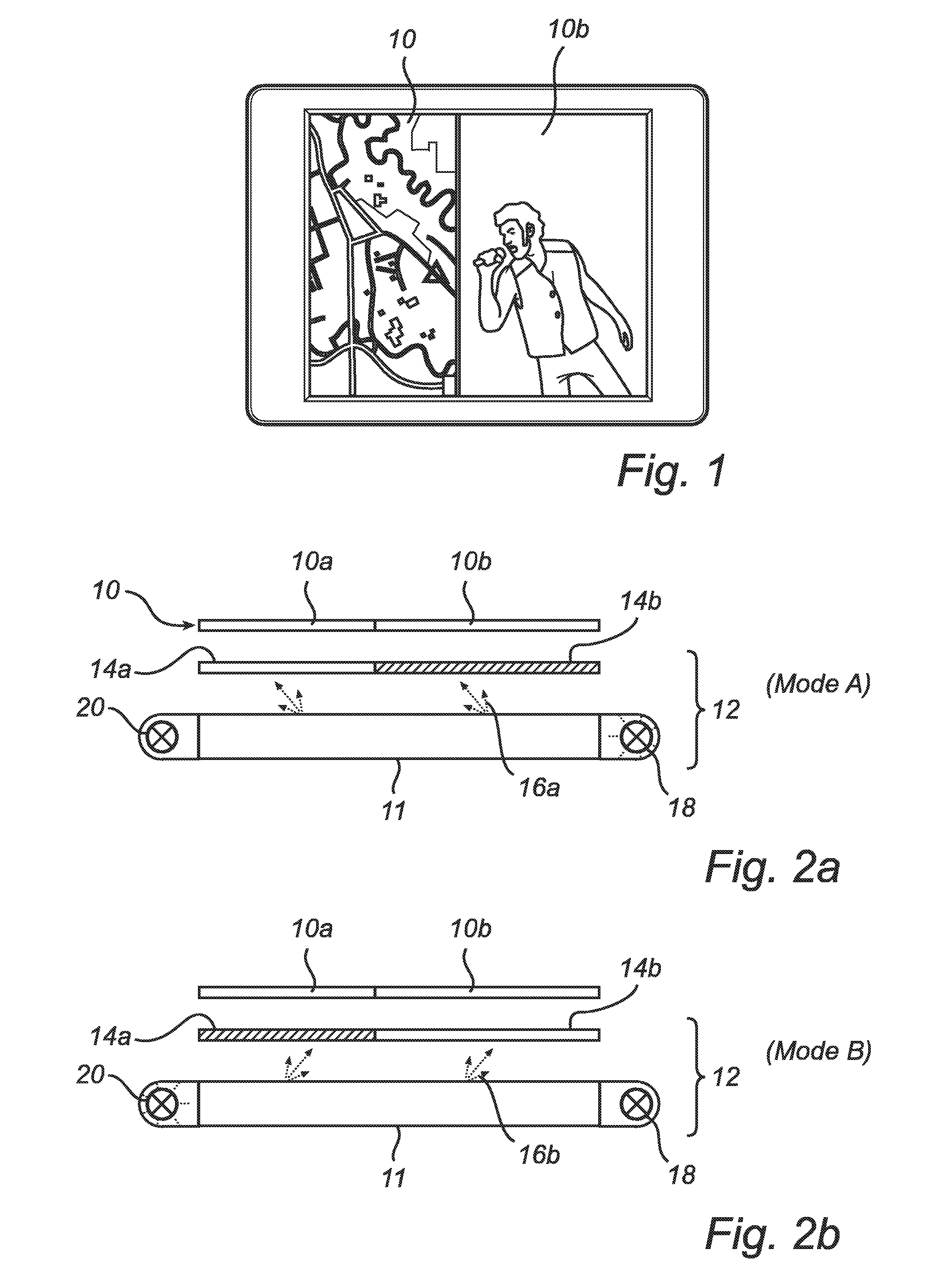
[0024]FIGS. 2a-2c illustrate schematically a cross section through a display device according to the invention in three different display modes. This cross section could be taken as seen from the bottom of FIG. 1.

[0025]Briefly, the display device comprises a transmissive LCD panel 10 and a backlighting arrangement 12.

[0026]The LCD panel 10 comprises a number of sub-layers such as polarizers, etc., as is well known in the art. As mentioned above, first and second sections 10a, 10b are arranged to display driver and passenger information, respectively.

[0027]The backlighting arrangement 12 comprises a lightguide 11, which is capable of selectively emitting light with a first or a second angular distribution.

[0028]FIG. 2a illustrates the display device in a first mode (Mode A). The lightguide may be devised similar to what is disclosed in WO, 2004 / 088996, A1. Then, when the lightguide 11 in Mode A is illuminated with light from a first light source 18 as illustrated in FIG. 2a, the ligh...

second embodiment

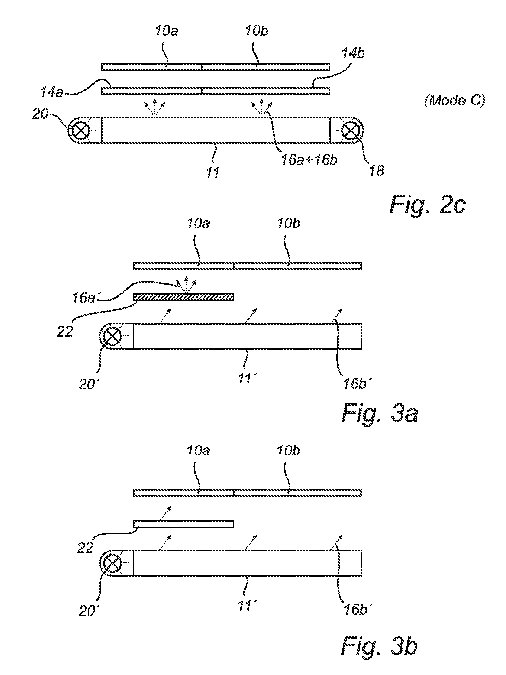
[0036]FIGS. 3a-3b illustrate schematically a similar cross section through a display device according to the invention in two different display modes. In this embodiment a light guide 11′ is constantly illuminated by at least one light source 20′. The light guide 11′ in turn therefore emits light with a constant angular distribution 16b′, which may be suitable for displaying an image in a direction towards a passenger. At the second sub-section 10b of the LCD panel, the display device therefore displays an image that is visible only from a position having a particular angular relationship vis-à-vis the display device. At the first LCD panel sub-section however, a diffuser 22 alters the angular distribution of the light into a another distribution 16a′, such that the first LCD panel sub-section 10a displays an image that can be viewed in a broader angular range than the second sub-section 10b. Information displayed on this part of the display area can therefore be viewed also e.g. by...


PUM


Abstract

The present invention relates to a dual view display device where a display surface is divided into a first and a second sub-section (10a, 10b). A backlighting arrangement is used which provides light with different angular distributions (16a, 16b; 16a′, 16b′) to the different sub-sections. This allows at low cost e.g. in a vehicle the displaying of movies or computer game windows at a part of a display, which part is not visible for the driver of the vehicle.

Description

FIELD OF THE INVENTION[0001]The present invention relates to a display device, being capable of displaying different content in different viewing angles and comprising an LCD panel and a backlighting arrangement.BACKGROUND OF THE INVENTION[0002]Such a device is disclosed e.g. in WO, 2004 / 088996, A1. This device is intended to be used as an autostereoscopic 3D display and comprises an LCD panel and a switchable backlighting arrangement, which is capable of providing backlight with two different angular distributions, one being suitable for displaying content to the right eye of a user, and another being suitable for displaying to the user's left eye. The backlight is switched between the two states, and at the same time the LCD panel is switched between showing right eye and left eye content.[0003]A disadvantage with such a display is the high speed requirements imposed on the LCD panel in order to achieve flicker-free displaying of information. These requirements result in a complex...

Claims


Application Information

Patent Timeline
IPC IPC(8): G09G5/00G09G3/36
CPCB60K35/00B60K2350/901B60K2350/903B60R2011/0005G02B6/0043G02B6/0051G02F1/1323G02F1/133615G02F2001/133391B60K2370/1526B60K2370/736B60K2370/739G02F1/133391
Inventor VISSENBERG, MICHEL CORNELIS JOSEPHUS MARIEIJZERMAN, WILLEM LUBERTUSBINASCH, GABRIELA
Owner KONINKLIJKE PHILIPS ELECTRONICS NV
Why Eureka
Try Eureka