Collecting chamber for a cleaning appliance

a collection chamber and cleaning technology, applied in the direction of cleaning equipment, cleaning filter means, suction filters, etc., can solve the problems of affecting the performance of the cleaning appliance, unwanted spillage of dirt and dust, etc., and achieve the effect of simple and convenient manufactur

Active Publication Date: 2011-08-16
DYSON TECH LTD
View PDF20 Cites 108 Cited by
  • Summary
  • Abstract
  • Description
  • Claims
  • Application Information

AI Technical Summary

Benefits of technology

[0014]Preferably, when the collecting chamber is held on the main body, a part of the main body is adapted and arranged to displace the displaceable member from the first position to the second position. More preferably, the displaceable member is rotatable between first and second positions. This arrangement is a simple and convenient way of providing a movable displaceable member.
[0015]Alternatively, the displaceable member is deformable between first and second positions. The displaceable member may be deformed by a part of the main body in order to move the displaceable member from the first position to the second position. Such an arrangement requires few components and is simple to manufacture.

Problems solved by technology

This prevents accidental opening of the closure member whilst the collecting chamber is located on the main body, which may result in unwanted spillage of dirt and dust and may affect the performance of the cleaning appliance.

Method used


Image

  • Collecting chamber for a cleaning appliance
  • Collecting chamber for a cleaning appliance
  • Collecting chamber for a cleaning appliance

Examples


Embodiment Construction

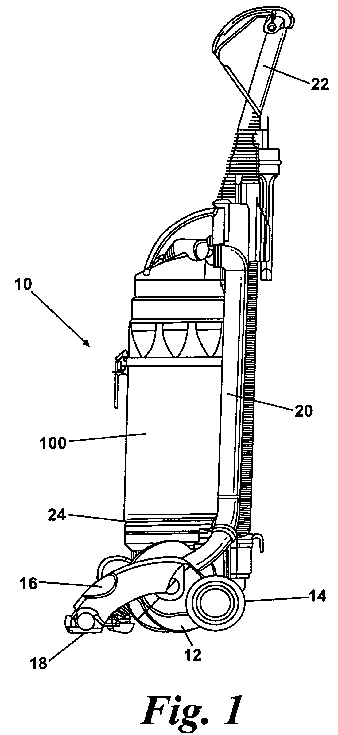
[0022]FIG. 1 shows an upright vacuum cleaner 10 having a main body 12 which includes a motor and fan unit (not shown) and a pair of wheels 14. A cleaner head 16 is pivotably mounted on the lower end of the main body 12 and a dirty air inlet 18 is provided in the underside of the cleaner head 16 facing the floor surface. The main body 12 further includes a spine 20 which extends vertically upward and merges into a handle 22. The handle 22 can be manipulated by a user to manoeuvre the vacuum cleaner 10 across a floor surface. The main body 12 further includes a plurality of outlet ports 24 for exhausting air from the vacuum cleaner 10.

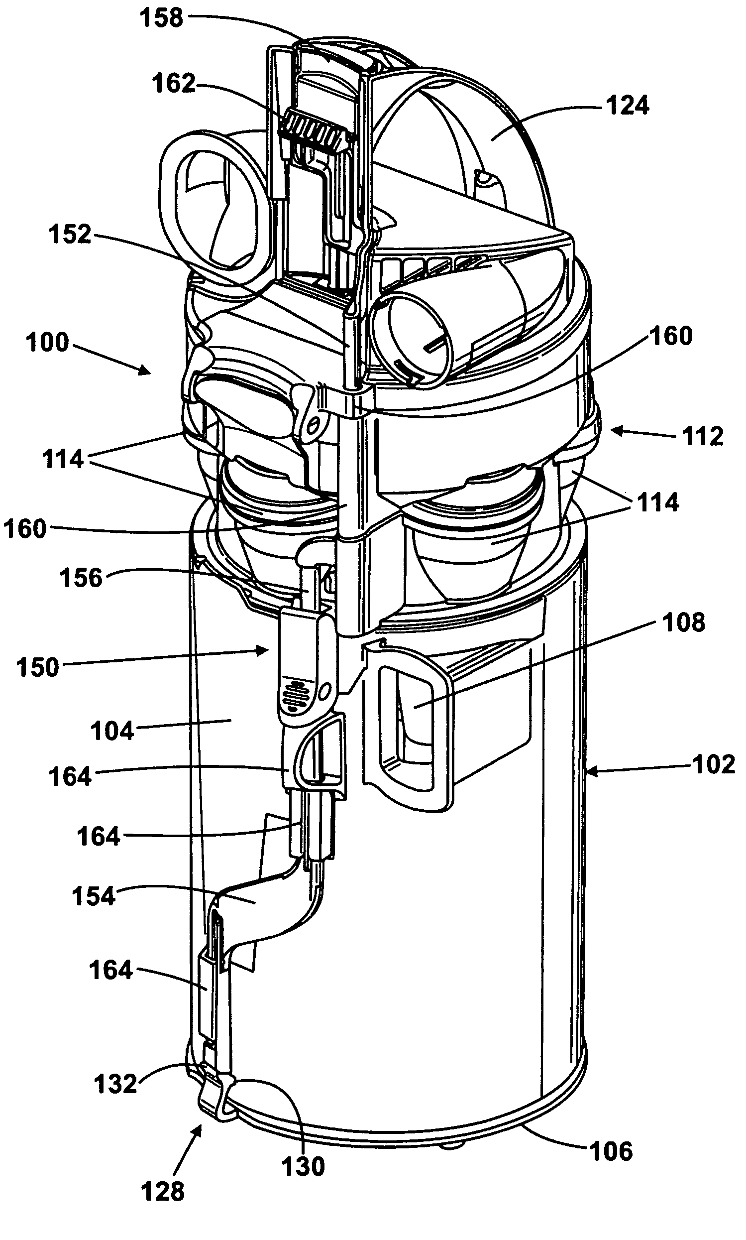
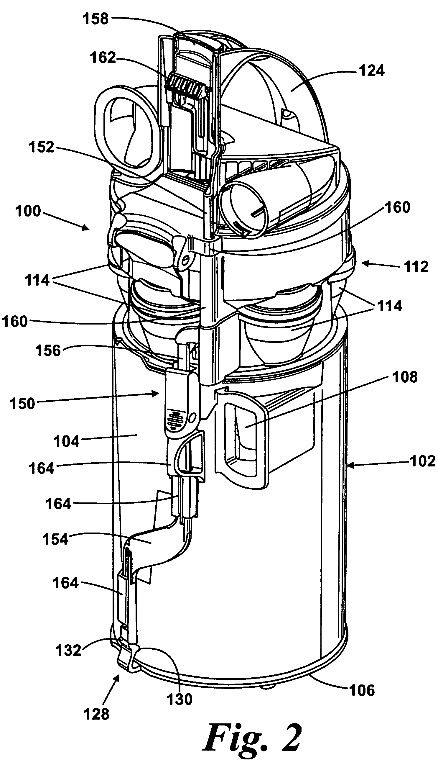
[0023]A collecting chamber 100 is releasably held on the main body 12. The collecting chamber 100 is supported on the main body 12 above the outlet ports 24 and lies adjacent the spine 20. The interior of the collecting chamber 100 is in communication with the dirty air inlet 18 through ducting in the spine 20. The collecting chamber 100 can be removed f...


PUM


Abstract

A cleaning appliance includes a main body and a collecting chamber releasably held on the main body. The collecting chamber includes a closure member which is movable between a closed position and an open position in which the collecting chamber can be emptied and an actuating member adapted and arranged to release the collecting chamber from the main body and, when the collecting chamber is released from the main body, to release the closure member from the closed position. By providing such an arrangement, a single actuating member can be used to release the collecting chamber from the main body of the cleaning appliance and also to open the closure member to empty the collecting chamber. A single actuating member is less complex, requires less space and is more intuitive for a user to operate.

Description

REFERENCE TO RELATED APPLICATIONS[0001]This application claims the priority of United Kingdom Application No. 0708536.8, filed May 3, 2007, the contents of which are incorporated herein by reference.FIELD OF THE INVENTION[0002]The present invention relates to a collecting chamber for a cleaning appliance. Particularly, but not exclusively, the present invention relates to a collecting chamber for a vacuum cleaner.BACKGROUND OF THE INVENTION[0003]Vacuum cleaners which utilise cyclonic separators are well known. Examples of such vacuum cleaners are shown in EP 0 042 723, EP 1 370 173 and EP 1 268 076. In general, an airflow in which dirt and dust is entrained enters a first cyclonic separator via a tangential inlet which causes the airflow to follow a spiral or helical path within a collecting chamber so that the dirt and dust is separated from the airflow. Relatively clean air passes out of the chamber whilst the separated dirt and dust is collected therein. In some applications, and...

Claims


Application Information

Patent Timeline
Patent Type & Authority Patents(United States)
IPC IPC(8): A47L9/10A47L9/20
CPCA47L9/106A47L9/1683A47L9/1691A47L9/10A47L9/16
Inventor WOOD, RALPH MICHAELELLAM, MATTHEW JAMESHARE, COLIN IRWIN
Owner DYSON TECH LTD
Why Eureka
Try Eureka