Fastener With Visual Indicator

a technology of visual indicators and fasteners, applied in the direction of rail fasteners, mechanical apparatus, roads, etc., can solve the problems of prolonging inspection duration, affecting the ability to readily distinguish between fasteners and materials, and reducing the identification difficulty of many common fasteners

a technology of visual indicators and fasteners, applied in the direction of rail fasteners, mechanical apparatus, roads, etc., can solve the problems of prolonging inspection duration, affecting the ability to readily distinguish between fasteners and materials, and reducing the identification difficulty of many common fasteners

US20080260496A1Inactive Publication Date: 2008-10-23PARMANN JASON B

Image

  • Fastener With Visual Indicator
  • Fastener With Visual Indicator
  • Fastener With Visual Indicator

Examples


Embodiment Construction

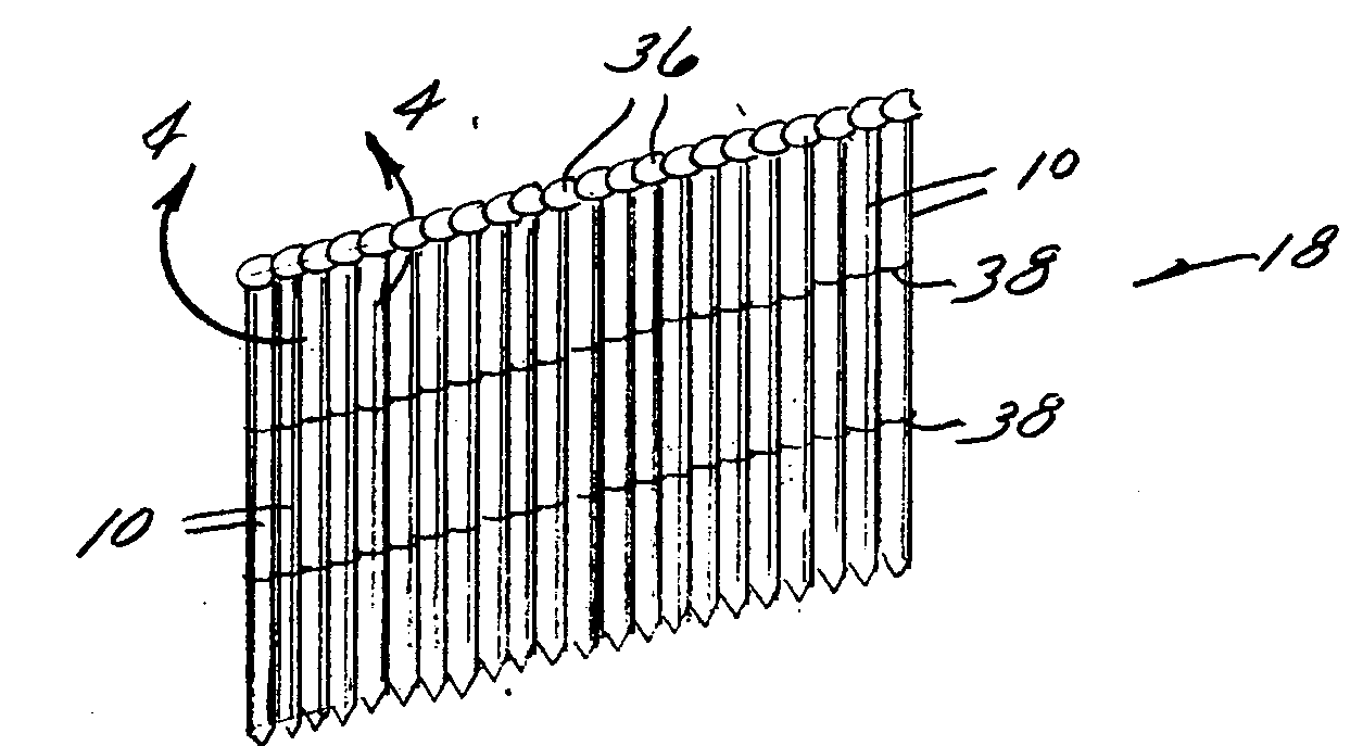
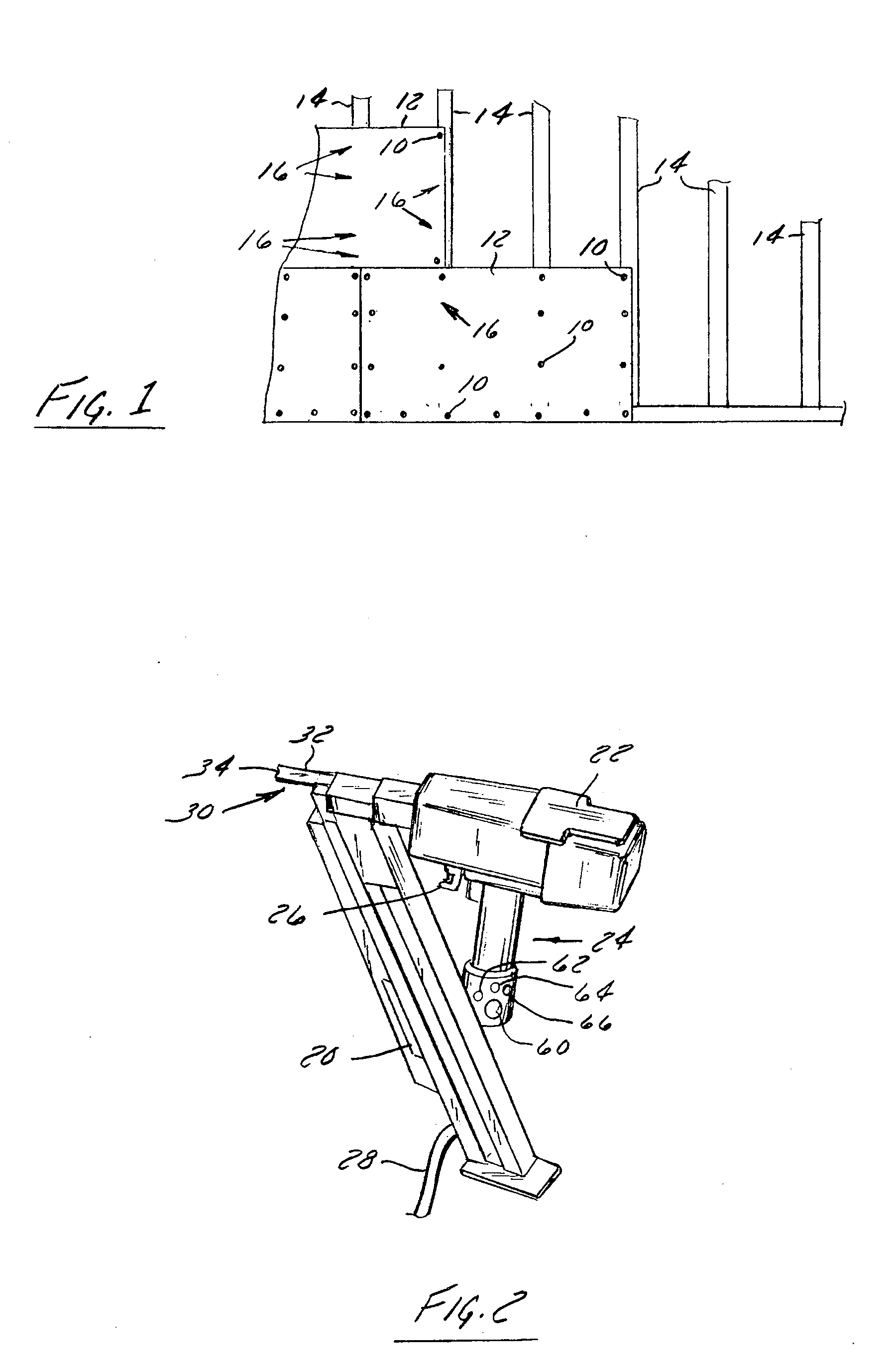
[0018]FIG. 1 shows a number of fasteners or nails 10 constructed according to the present invention. As shown in FIG. 1, nails 10 secure a first material or structure, such as sheathing 12 to a second material or structure, or a stud wall 14. It is appreciated that nails 10 can be used to connect a variety of construction materials where it is desired to be able to reaasily inspect the placement of the fasteners. It is appreciated that other structures, such as rough framing, hangers, sill plates, top plates, and headers may be secured with fasteners constructed according to the present invention. It is further appreciated that although structures 12, 14 are shown as what is commonly understood as orientated strand board (OSB) and dimensional lumber, nails 10 can be used to secure various types, shapes, and sizes of materials including, foam materials, cementations products, wall board, plastic materials, etc. It is also appreciated that nails according to the present invention coul...


PUM


Abstract

A fastener that includes a head portion and a body and is configured to be driven into material. The body is configured for engaging the material and the head portion is constructed to be engaged by a driver of a power nailer. A color coating is applied to a face of the head portion for visually locating fasteners engaged with the material

Description

CROSS-REFERENCE TO RELATED APPLICATION[0001]This application claims priority to provisional application U.S. Ser. No. 60 / 912,322 filed on Apr. 17, 2007 and titled “FASTENER WITH VISUAL INDICATOR.”BACKGROUND[0002]This invention relates to mechanical fasteners, and more particularly, to nails constructed to be driven by nail guns. Various construction tasks require securing one member to another. Any of a number of common fasteners can be used to secure together adjacent members. In the construction trades, these fasteners are frequently provided as either of screws or nails. In planned structure construction, the interface between various elements of the structure, such as a stud wall, sill plates, top plates, headers, hangers, sheathing, etc., are generally specified by various building codes or other structural standards. To provide some surety as to the integrity and the quality of the structure, many municipalities require structures be periodically inspected or checked to confir...

Claims


Application Information

Patent Timeline
23 Oct 2008
Publication
US20080260496A1
IPC
F16B15/00
CPC
F16B1/0071; F16B15/08; F16B2200/95
Inventors
PARMANN, JASON B.