Fire damper

a damper and fire technology, applied in the field of fire dampers, can solve the problems of adversely affecting the time period of the louver and thereby the damper, and achieve the effect of reducing the damage of the fir

Inactive Publication Date: 2008-10-30
RUSKIN COMPANY
View PDF17 Cites 12 Cited by
  • Summary
  • Abstract
  • Description
  • Claims
  • Application Information

AI Technical Summary

Problems solved by technology

Such construction adversely affects the period of time that the louver, and thereby the fire damper, can resist failure caused by hot gases from a fire.

Method used


Image

  • Fire damper
  • Fire damper
  • Fire damper

Examples


Embodiment Construction

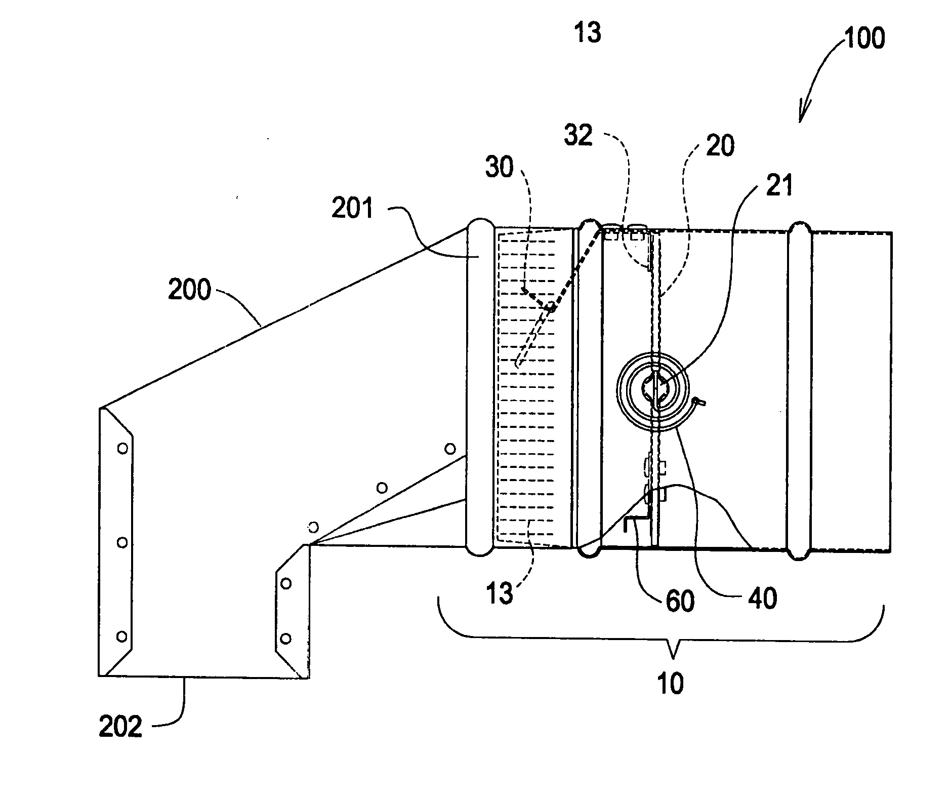
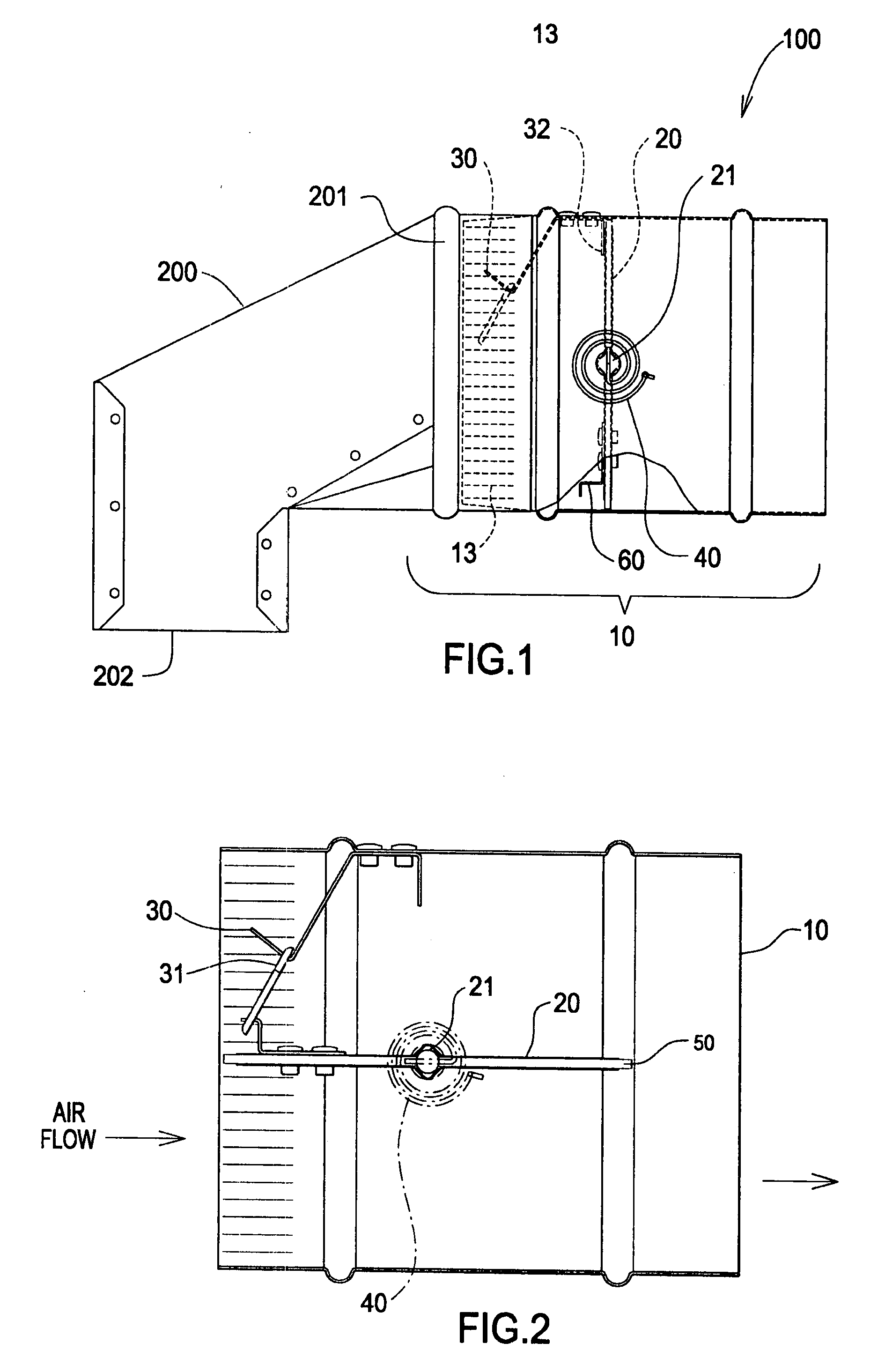
[0017]FIG. 1 is a side view of the fire damper. Fire damper 100 comprises a housing 10. Housing 10 comprises metallic ductwork known in the art, for example, galvanized 22 gauge. In the present embodiment, the housing is circular.

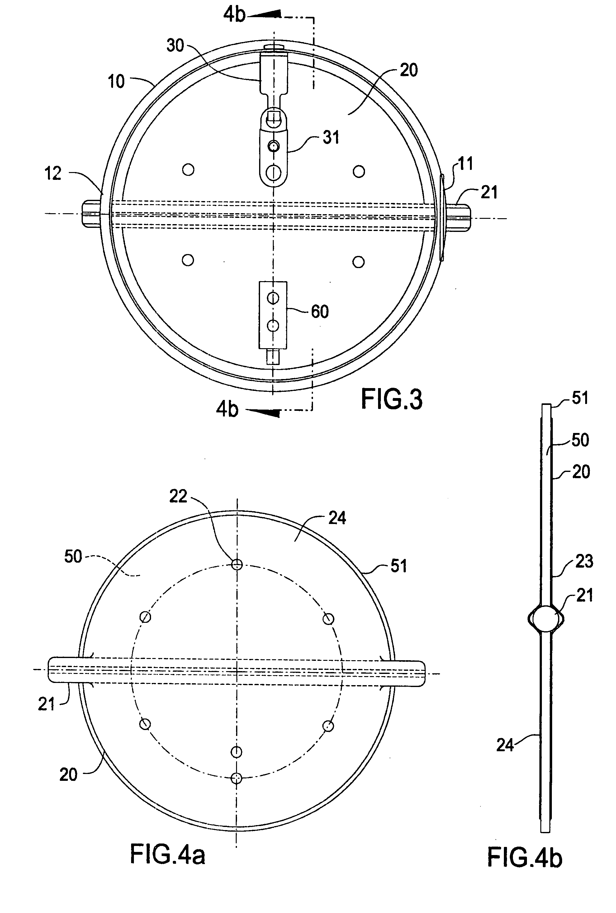
[0018]Disposed within housing 10 is louver member 20. Louver member 20 is mounted to a shaft 21. Shaft 21 rotates within housing 10. Rotation of shaft 21 allows louver member 20 to pivot between an open position and a closed position.

[0019]Member 60 is attached to louver member 20 and is used to connect louver member 20 to temperature sensitive connector 31, see FIG. 2.

[0020]Louver member 20 is shown in the closed position in FIG. 1. In the closed position louver member 20 provides a substantially gas tight seal for a predetermined temperature, and at a differential pressure of up to 15 inches of water.

[0021]Biasing member 40 is engaged between shaft 21 and housing 10. Biasing member 40 biases louver member 20 toward the closed position as is shown in FIG. ...


PUM


Abstract

A fire damper comprising a housing, a louver member rotationally engaged within the housing, the louver member having a substantially gas tight seal with the housing when the louver member is in a closed position, a biasing member disposed outside of the housing and engaged with the louver member for moving the louver member from an open position and holding the louver member in the closed position, a temperature sensitive member releasably connected to the louver member, the temperature sensitive member for releasing the louver member from the open position at a predetermined temperature, and the louver member further comprising insulation material to control heat transfer through the louver member for a predetermined period of time.

Description

FIELD OF THE INVENTION[0001]The invention relates to a fire damper, and more particularly, to a fire damper having a fusible link, and a normally open, thermally insulated rotating louver connected to an external biasing member.BACKGROUND OF THE INVENTION[0002]Fire dampers are used to seal an air handling system from a space experiencing a fire, thereby preventing any backflow of oxygen to the space through the ductwork. Sealing the ductwork deprives the fire of oxygen.[0003]Fire dampers may generally comprise louvers, but, such louvers comprise simple metallic sheets. Such construction adversely affects the period of time that the louver, and thereby the fire damper, can resist failure caused by hot gases from a fire.[0004]Representative of the art is U.S. Pat. No. 4,559,867 to VanBecelaere (1985) which discloses a transversely circular fire damper having a butterfly type blade operated by a jack shaft spaced longitudinally of the housing from the blade axle. Linkage including an “...

Claims


Application Information

Patent Timeline
Patent Type & Authority Applications(United States)
IPC IPC(8): F23N3/04
CPCA62C2/241A62C2/12F24F2011/0098F24F11/35
Inventor VAN BECELAERE, ROBERT M.
Owner RUSKIN COMPANY
Why Eureka
Try Eureka