Reinforced Soil Retaining Wall System and Method of Construction

Inactive Publication Date: 2008-10-30
MODALCO
View PDF5 Cites 15 Cited by
  • Summary
  • Abstract
  • Description
  • Claims
  • Application Information

AI Technical Summary

Benefits of technology

[0034]a second plurality of sections of soil reinforcement for stabilizing a quantity of backfilled and compacted soil on the retained side of the wall, the second plurality of sections of so

Problems solved by technology

Gravity retaining walls cost more money to install, which eac

Method used


Image

  • Reinforced Soil Retaining Wall System and Method of Construction
  • Reinforced Soil Retaining Wall System and Method of Construction
  • Reinforced Soil Retaining Wall System and Method of Construction

Examples


first embodiment

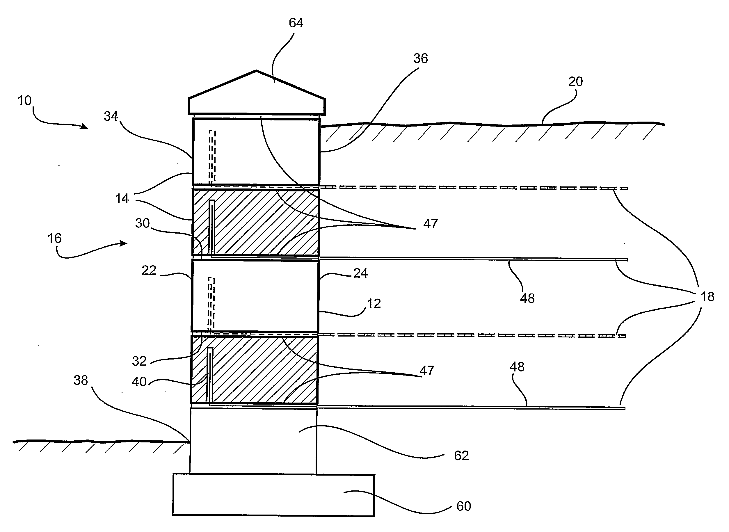
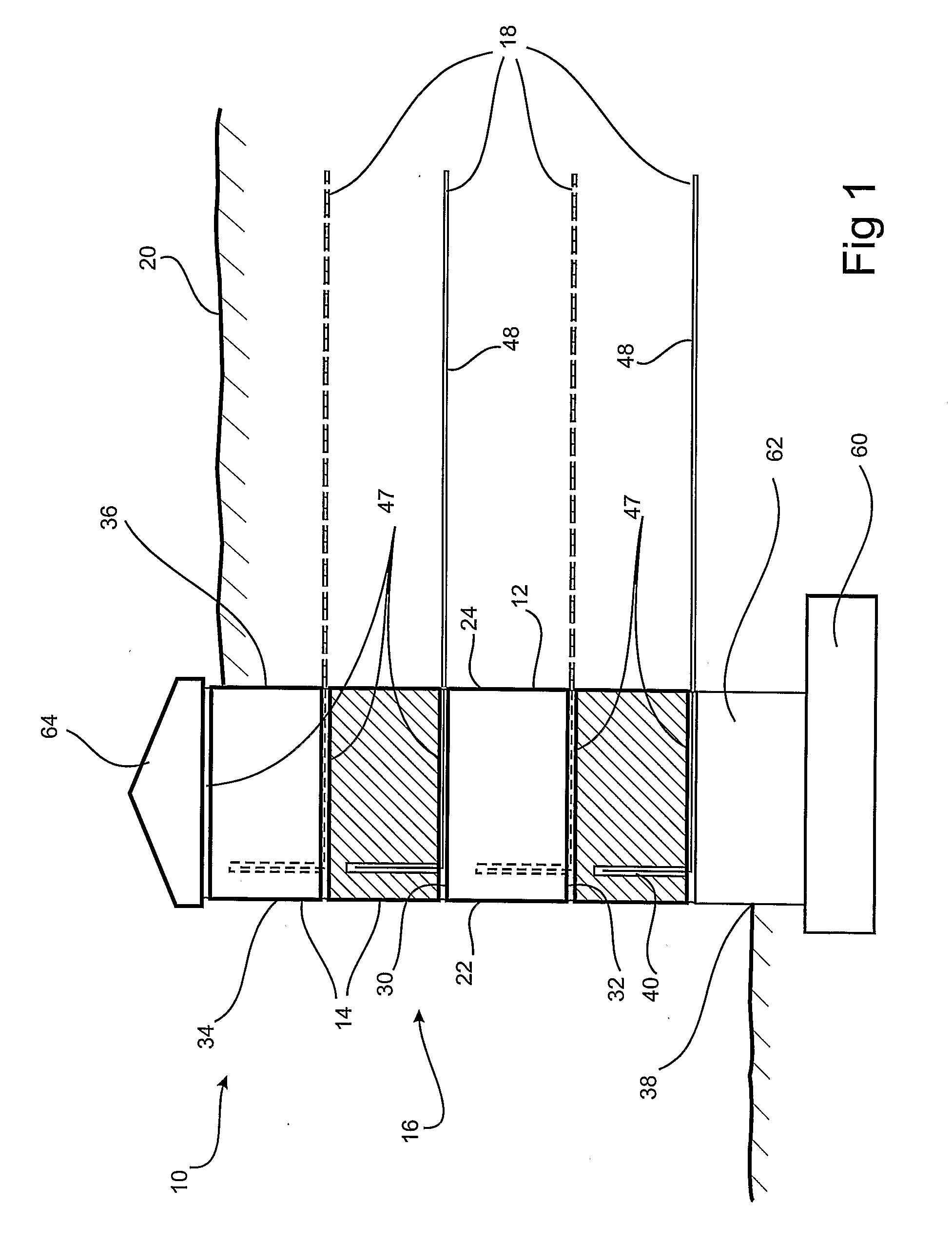
[0077]the reinforced soil retaining wall system 10 of present invention is now described with reference to FIGS. 1 to 7, the reinforced soil retaining wall system 10 comprising a plurality of blocks 12 arranged in courses 14 to form a wall 16. Soil reinforcement is provided to the wall 16 using a plurality of lengths of strip reinforcement 18 inserted in and extending from the blocks 12, the strip reinforcement 18 being buried under compacted backfill 20 either as each course 14 is laid or after construction of the wall 16.

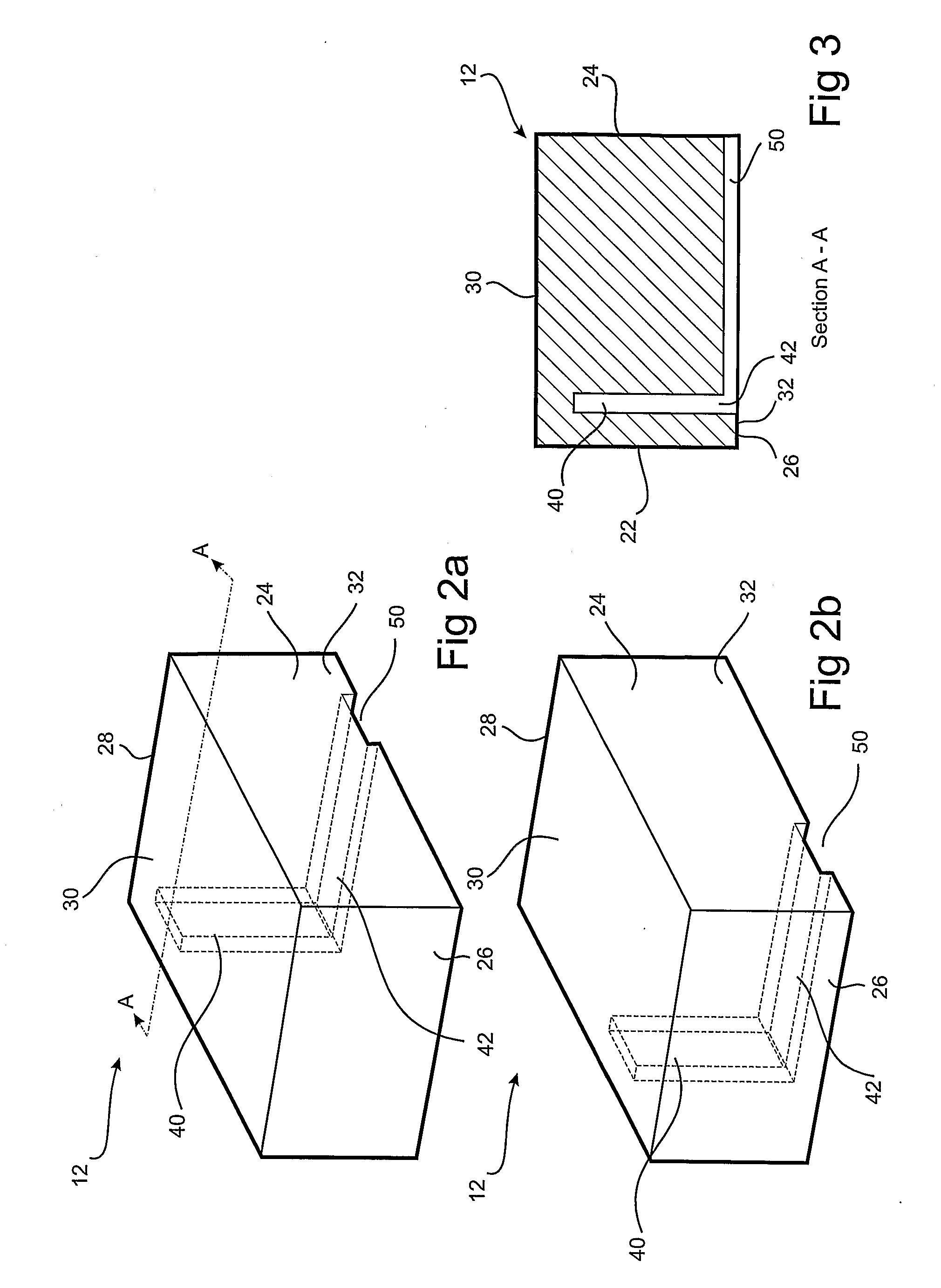
[0078]With reference to FIGS. 1, 2(a) and 2(b), the blocks 12 used in accordance with a first embodiment of the reinforced soil wall system 10 comprise a front face 22, a rear face 24 spaced from said front face by a distance defining the depth of the block 12, opposing side surfaces 26 and 28 respectively, spaced from each other by a distance defining the width of the block 12, a top surface 30 and a bottom surface 32 spaced from the top surface 30 by a distance ...

third embodiment

[0109]This based on a realization that the top 0.1-0.9 meters of the retaining wall is effectively self-supporting. The transition depth 92 depends in part on the anticipated depth of any installations or structures to be constructed on the retained side of the wall, but it is anticipated that the transition depth will not exceed one metre and will more likely be around 0.4 to 0.6 m below the final anticipated height of the composite wall 90.

[0110]A soil reinforcement protection barrier 98 may be installed at the transition depth 92 in general coplanar alignment with respect to the top surface 30 of the uppermost course 14 of the lower section 96. The barrier 98 serves as a visual or physical barrier to protect the strip reinforcement 18 from damage during subsequent building operations adjacent to the completed retaining wall. Accordingly, the barrier 98 may take the form of a thin planar strip of plastic that provides a visual indication that the transition depth has been reached ...

fourth embodiment

[0111]the system 10 and blocks 12 of the present invention is illustrated in FIGS. 12 and 13 for which like reference numerals refer to like parts. This embodiment has been designed specifically to deal with problems associated with using backfill such as clay soils which have a very slow rate of permeation of water. As a result of the low permeability of the soil, the backfill 20 may become saturated over time, for example due to precipitation, resulting in a buildup in water being stored on the retained side 32 of the wall 16. This causes hydrostatic pressure on the wall 16 to increase, effectively pushing against the retained side 32 of the wall 16.

[0112]One way to overcome this problem is to place a vertically oriented permeable layer 104 of permeable material such as drainage aggregate adjacent to the retained side 32 of the wall 16 to allow water to drain under gravity from behind the wall through a drainage channel 106 positioned towards the base of the wall 16 and extending ...


PUM


Abstract

A reinforced soil retaining wall system (10) in which a plurality of blocks (12) are arranged in courses (14) to form a wall (16). Soil reinforcement is provided to the wall (16) using a plurality of lengths of strip reinforcement (18) inserted in and extending from the blocks (12), the strip reinforcement (18) being buried under compacted backfill (20) either as each course (14) is laid or after construction of the wall (16). Also disclosed is the use of a second plurality of sections of soil reinforcement, spaced apart from the first plurality of sections and arranged to extend perpendicular to the wall.

Description

FIELD OF THE INVENTION[0001]The present invention relates to a reinforced soil retaining wall system and a method of construction of a reinforced soil retaining wall. The present invention further relates to a block used in the construction of a reinforced soil retaining wall and a length of strip reinforcement used in the construction of a reinforced soil retaining wall.[0002]The present application claims priority from Australian provisional patent application 2004901725 filed on 1 Apr. 2004, Australian provisional patent application 2004901789 filed on 5 Apr. 2004, Australian provisional patent application 2004907121 filed on 15 Dec. 2004 and Australian provisional patent application 2005900832 filed on 23 Feb. 2005.BACKGROUND TO THE INVENTION[0003]Retaining walls are defined as any wall that restrains material on one side of a wall to maintain a difference in elevation. Nearby slopes, driveways, buildings, and tiered walls all represent potential loads on retaining walls. There ...

Claims


Application Information

Patent Timeline
IPC IPC(8): E02D29/02E02D5/76E02D17/20
CPCE02D29/0225E02D29/0233
Inventor COSTIN, SAMUEL PATRICK
Owner MODALCO
Why Eureka
Try Eureka