Method for jet formation and the apparatus for the same

a jet and liquid technology, applied in the direction of positive displacement liquid engines, machines/engines, manufacturing tools, etc., can solve the problems of unnecessary or even damaging jet geometry change, excessive energy consumption and material losses, needless losses of energy and material, etc., to achieve minimal hydraulic resistance of the slot, easy restoration, and maximize the effect of resistan

Inactive Publication Date: 2006-05-16
GESKIN ERNEST +1
View PDF14 Cites 0 Cited by
  • Summary
  • Abstract
  • Description
  • Claims
  • Application Information

AI Technical Summary

Benefits of technology

[0011]A further object of this invention is to provide the means for rapid inexpensive change of the worn parts of the nozzle.
[0013]It is also object of this invention to utilize the combination of the liquid compression prior to the slot nozzle, rapid decompression I at the entrance of the slot and the negligible thermal and diffusion resistance of the flow in the slot in order to use the slot as a reactor for material production, for example for water decomposition into hydrogen and oxygen.
[0014]To achieve the forgoing and other objects and in accordance with purpose of the present invention as described herein, the invention advances the teaching of the prior art by providing an inexpensive well sealed nozzle assembly comprising two attached plates and containing a port for supply of a fluid, for example water, a slot for dispensing the fluid and the channels connecting this port with a slot. The form of the slot can readily vary to generate a high speed jet of a desired geometry. The jet geometry is determined by the form of the slot obtained in the course of inexpensive machining of the plates. In order to prevent the leaks of the fluids from the nozzle the hydraulic resistance of the slot is minimal while the hydraulic resistance of the plates contact is maximal. In order to maximize the resistance the contact surfaces of the plates are well polished and the plates are connected by a set of fasteners, glued or brazed. The deformation of the plates induced by fasteners secures the sealing of the nozzle and controls the slot geometry. A worn nozzle can be readily restored by polishing of the contact surfaces and machining of the slot area.
[0015]The sealing of the nozzle can be improved by a multilayer insertion separating the plates. The shape of the insertion determines the length of the slot, a number and thickness of the layers determines the height of the slot, while the deformation of the insertion secures the sealing of the nozzle. The slot can be formed by two insertions into the plates normal to the direction of the flow. The insertions are fabricated out of a wear resistant material and are readily replaceable.
[0016]The fluid can be periodically compressed in a reservoir by forces applied to the plates and deforming them. This results in the formation of a pulse jet, which has well known technological advantages. Different fluids and particles can be added into the reservoir or entrained into the jet in special chambers accommodating the jet exiting the slot. The shape of the jet enhances the process of the entrainment.
[0018]Also according to this invention a set of conditions which can be developed in the slot (fast decompression, feasibility of the fast cooling or heating, feasibility to induce strong magnetic and electrical field, feasibility to attain close contact with catalic media or introduce an another reactant) enable us to use the slot as a reactor for material production.

Problems solved by technology

But in the case of the omni directional round jet the increase of the useful dimension brings about unnecessary or even damaging change of the jet geometry.
Increase of the width of a saw beyond the level, which assures its strength, results in the excessive energy consumption and material losses.
Similarly, excessive diameter of the cutting jet brings about the needless losses of energy and material.
Excessive jet diameter in the course of surface processing, similarly to an excessive width of a brush, increases energy consumption.
Thus, generation of the homogeneous surface in the course of the processing using the round jet is difficult if not impossible.
Still another shortcoming of the round nozzles is impossibility to repair a worn nozzle.
However due to the intensive wear these nozzles rapidly lose their integrity and thus cannot last sufficiently long.
Besides, the formation of a precision shaped orifice in a hard solid material is an expensive operation.

Method used


Image

  • Method for jet formation and the apparatus for the same
  • Method for jet formation and the apparatus for the same
  • Method for jet formation and the apparatus for the same

Examples


Embodiment Construction

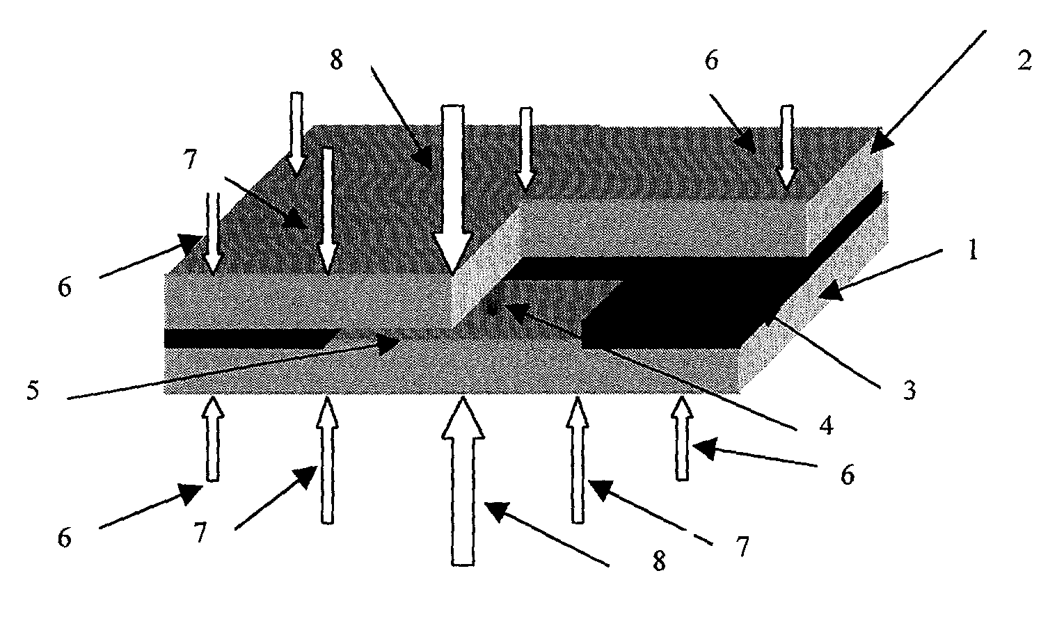
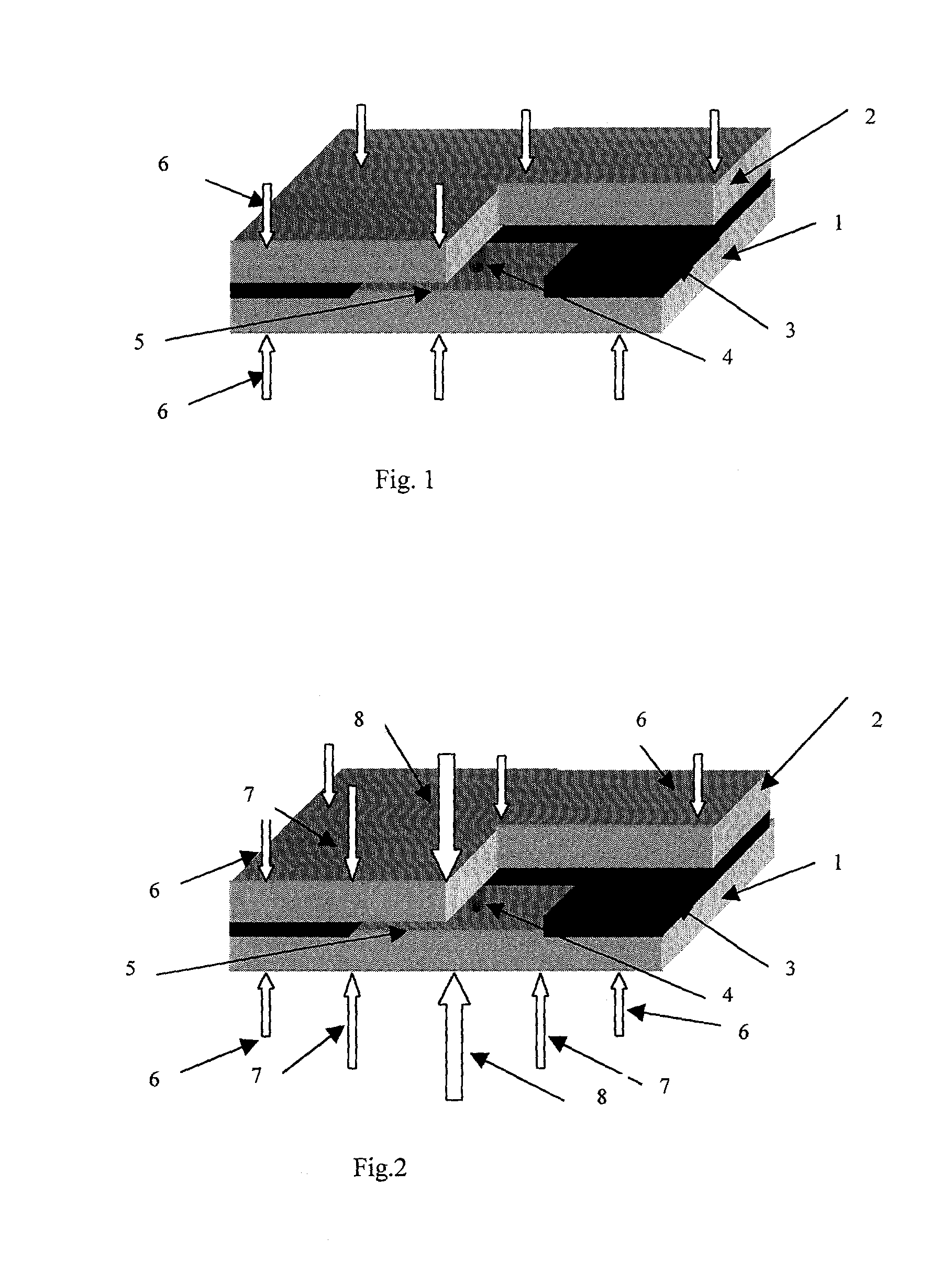
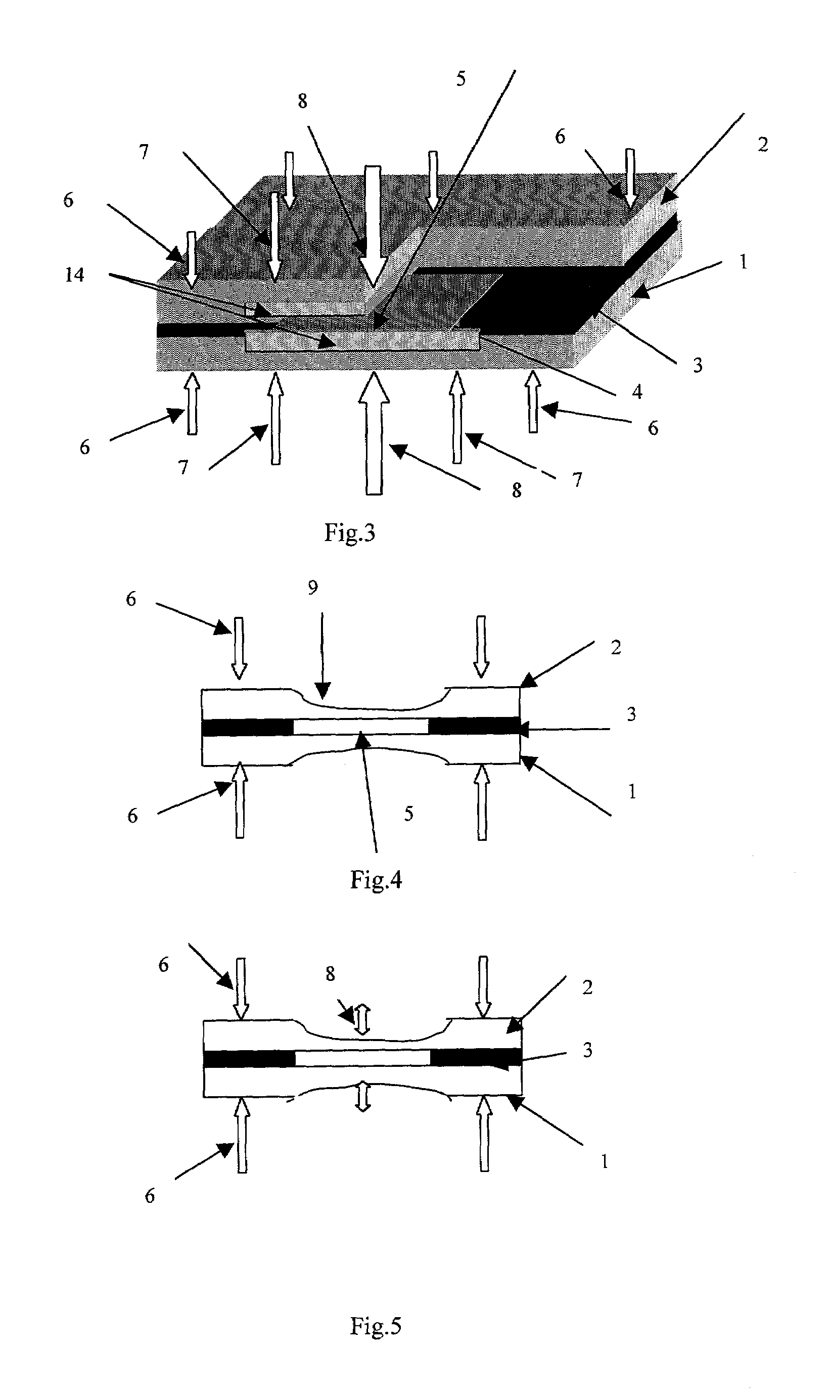
[0030]As it is shown in FIG. 1 the low 1 and the upper 2 plates are separated by the insertion 3. In this nozzle a fluid being accelerated flows from the inlet 4 to the exit 5. The shape of the channels in the nozzle assures gradual conversion of a round jet entering the nozzle into the slot type flow exiting the nozzle via the opening 5. The most important stage of the jet formation occurs at the vicinity of and within the slot. The opening might contain the converging, straight and diverging regions. The geometry of these regions is selected so that the head losses in the course of the jet formation are minimal. The geometry of the channel containing the fluid including the geometry of the exit cross section is determined by the shapes of plates 1 and 2 and the insertion 3. According to the present invention the width of the opening can be controlled by the geometries of the plates 1 and 2 or the geometries of the insertion 3 which separates plates 1 and 2. The cut off of the inse...


PUM


Abstract

The method of and the apparatus for the formation of a high-speed fluid or slurry jets of a desired geometry are invented. According to the present invention a fluid or slurry jet is formed by the expelling of a compressed fluid via a slot formed by two attached plates separated by the insertion. The shape of the slot is determined by the forms of the plates and the insertion. This shape is also determined by the deformation of the plates and the insertion by the external forces applied to the plates, for example by the fasteners connecting the plates.

Description

FIELD OF THE INVENTION[0001]The present invention relates to the method and device for formation of the high-speed liquid and slurry jets, more particularly to optimal control of the jet geometry.BACKGROUND OF THE INVENTION[0002]In recent years high-speed fluid and slurry jets have become a conventional tool in manufacturing, infrastructure maintenance and environment protection. A number of new non-traditional jet applications are emerging in mining, medicine and defense. These applications range from demolition of buildings and breakage of stones to eye surgery, from cleaning of the ocean bottom and deicing the roads to precision machining.[0003]Conventionally the jets are formed by expelling a compressed fluid through an opening in a metal or ceramic body termed a nozzle. In most cases the openings are round. This geometry is determined by the conditions of the nozzle fabrication. It is much easier to generate a round opening in a solid body than an opening of any other geometry....

Claims


Application Information

Patent Timeline
Patent Type & Authority Patents(United States)
IPC IPC(8): F04B43/14B05B1/04B05B1/14B24C5/04B26F3/00
CPCB05B1/04B05B1/044B26F3/004B24C5/04B05B1/14
Inventor GESKIN, ERNESTGOLDENBERG, BORIS
Owner GESKIN ERNEST
Why Eureka
Try Eureka