Temperature measuring device

a temperature measurement and device technology, applied in the direction of electrical control, exhaust treatment electric control, instruments, etc., can solve the problems of affecting the accuracy of temperature measurement, and adding wires and associated connections to the wires used for control, etc., to achieve clear improvement of accuracy

Active Publication Date: 2020-12-08
VITESCO TECH GERMANY GMBH
View PDF39 Cites 0 Cited by
  • Summary
  • Abstract
  • Description
  • Claims
  • Application Information

AI Technical Summary

Benefits of technology

[0008]The invention provides an innovative temperature measuring device that does not have the drawbacks of the prior art, in that it allows the addition of a measurement means, allowing a clearly improved accuracy, without the need for an additional wire between the control unit and the member.

Problems solved by technology

These wires and the associated connections are, detrimentally, added to the wires used for control.
Consequently, this approach most often does not allow very accurate temperature measurement.

Method used


Image

  • Temperature measuring device

Examples


Embodiment Construction

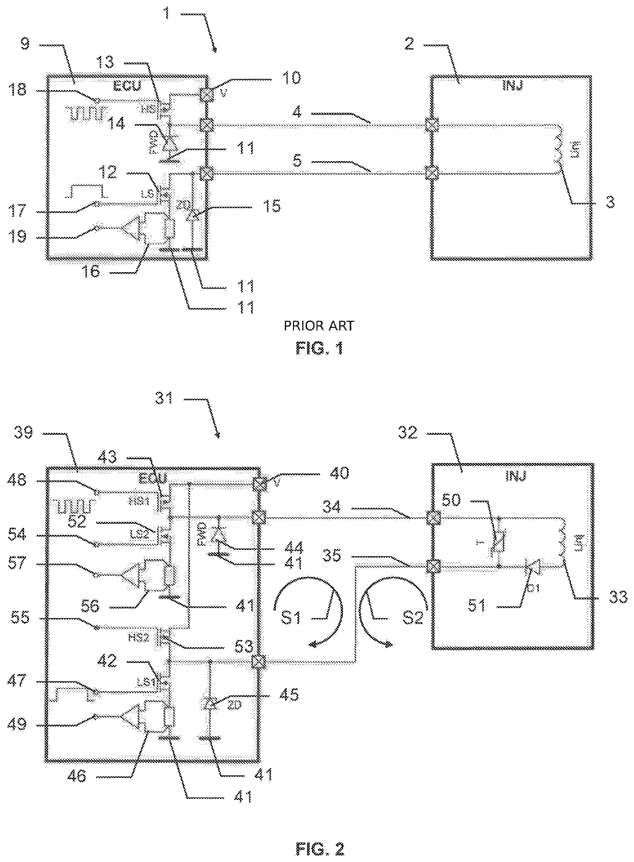
[0021]FIG. 1 illustrates a device 1 according to the prior art, including a member 2 and its control unit 9. The member 2 includes a component 3 the terminals of which are each connected to a wire 4, 5. These two wires 4, 5 are connected at the other end of same to the control unit 9.

[0022]The control unit 9 is capable of producing a control signal capable of controlling the component 3. The control of the component 3 by the control unit 9 is characterized in that it uses two wires 4, 5 and in that it is not continuously active. Thus the control signal transmitted by the control unit 9 to the member 2 is only active a part of the time, known as the activity time and which includes at least one activity interval. Each of said activity intervals is limited in that it is not continuous. Thus said activity intervals free up at least one interval free of a control signal.

[0023]A control signal may be any not necessarily continuous signal. It may be a coded digital type of control signal,...


PUM

PropertyMeasurementUnit
temperatureaaaaaaaaaa
temperature measuringaaaaaaaaaa

Abstract

Temperature measuring device for measuring the temperature of a member, the member including a component controlled by a control signal, active at most during at least one limited activity interval, and transmitted to the component via two wires, a temperature probe connected to the two wires, in parallel with the component, and a diode, connected between a terminal of the component and a terminal of the probe connected to the same wire, in order to allow the passage of a current in the component only in a first direction, the temperature measurement being performed by a current flowing in a second direction, opposite to the first direction, outside of the activity interval.

Description

BACKGROUND OF THE INVENTION[0001]The present invention relates to a temperature measuring device.[0002]Temperature often conditions the behavior of a member. Consequently, a measurement of the temperature of a member may be useful to a control unit of such a member, typically for adapting the control of the member.[0003]Such a member includes at least one controlled component. This component is connected to the control unit by means of at least two wires in order to be able to receive a control signal from the control unit.[0004]It is known, in order to provide a temperature measurement, to add a temperature measurement means close to the member or to integrate same into the member. Such a measurement means generally requires the addition of at least two wires in order to power the measurement means and to perform the temperature measurement. These wires and the associated connections are, detrimentally, added to the wires used for control.[0005]The controlled component generally ha...

Claims


Application Information

Patent Timeline
Patent Type & Authority Patents(United States)
IPC IPC(8): G01K13/00F02M57/00F02M51/00F01N3/20F02D41/20G01K7/22G01K7/25F01N9/00
CPCF02D41/20F02M51/005F01N3/208F02M57/005G01K7/22G01K7/25F02D2041/2027F01N2900/1811F01N2610/1453G01K2205/00F02D2041/2072F01N3/2066F02D2041/2065F01N9/00F01N2900/1821
Inventor BARBIER, PASCALROCHER, JACQUES
Owner VITESCO TECH GERMANY GMBH
Why Eureka
Try Eureka