Permanent magnetoresistive speed reducer

A technology of reducer and permanent magnet, which is applied in the field of vehicle auxiliary braking devices, military vehicles and aircraft auxiliary braking, and can solve the problem of slow response time of hydraulic retarder manipulation, limited engine exhaust braking torque, engine Increase fuel consumption and other issues to achieve the effect of quick response, simple and convenient control, and convenient installation

Pending Publication Date: 2019-01-18
邵金泽
View PDF0 Cites 0 Cited by
  • Summary
  • Abstract
  • Description
  • Claims
  • Application Information

AI Technical Summary

Problems solved by technology

[0002] With the development of today's society, the performance of automobiles is constantly improving, and the requirements for vehicle braking performance are increasing day by day. Traditional auxiliary braking includes engine exhaust braking, hydraulic retarder and electromagnetic eddy current retarder. Although they can basically meet the requirements of heavy trucks and The need for auxiliary braking of engineering vehicles, but they all have some defects more or less, such as engine exhaust braking, when the vehicle encounters a long-distance continuous downhill slope, the huge inertia of the heavy-duty truck will push the engine to run at high speed and make noise It is very large. At the same time, the exhaust brake does not work when the vehicle is running at low speed and the braking torque of the engine exhaust brake is also very limited. The hydraulic retarder and the eddy current retarder will consume the energy of the engine and increase the fuel consumption. At the same time, the response time of the hydraulic retarder is relatively slow, so we urgently need to develop a new concept of permanent magnet reluctance retarder that is different from the engine exhaust brake, hydraulic retarder and eddy current retarder. The natural reluctance effect formed by the stator and the rotor assists the braking of the vehicle. It not only has a strong braking torque but also does not consume the energy of the engine. No matter whether the vehicle is at low speed or high speed, the permanent magnet co-reluctance reducer can always brake the vehicle Maintain a constant braking torque while handling quickly, assisting the main vehicle braking system to perform deceleration braking

Method used


Image

  • Permanent magnetoresistive speed reducer
  • Permanent magnetoresistive speed reducer
  • Permanent magnetoresistive speed reducer

Examples


Embodiment Construction

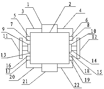
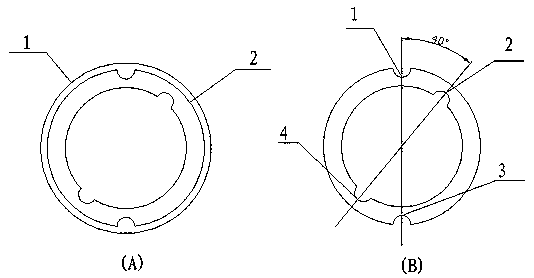
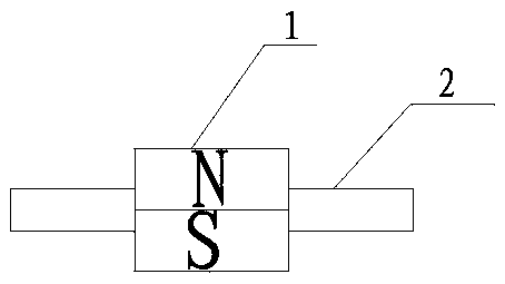
[0019] A permanent magnet reluctance reducer is composed of: a permanent magnet bipolar rotor, a stator, a rotor shaft, a bearing seat (including bearings), a main engine shell, a front end cover, a rear end cover, an upper magnetic guide rod, a lower magnetic guide rod, The upper two-way hydraulic valve, the lower two-way hydraulic valve, the upper push rod, the lower push rod, the input end flange, the output end flange, etc. The mutual position and assembly relationship are as follows: the permanent magnet bipolar magnet is assembled on the rotor shaft Composition of permanent magnet bipolar rotor assembly image 3 , the rotor shaft (14) is connected to the front end cover (13) and the rear end cover (15) respectively through the front bearing seat (9) and the rear bearing seat (10), and the front and rear end covers are respectively connected to the casing (2). figure 1 , see stator figure 2 , the stator is connected with the host shell (2), the upper two-way hydraulic v...


PUM


Abstract

A permanent magnetoresistive speed reducer is composed of a permanent magnet bipolar rotor, stator and rotor shaft, Bearing housing (including bearing), Host shell, Front cover, rear cover, upper magnetic rod, lower magnetic rod, upper bi-directional hydraulic valve, lower bi-directional hydraulic valve, upper push rod, lower push rod, input flange, output flange, etc. Permanent magnetoresistive reducer is a new concept of vehicle auxiliary braking device for heavy trucks, engineering vehicles and military vehicles and aircraft to provide auxiliary braking.

Description

technical field [0001] The invention relates to the field of automobile deceleration braking, and is a vehicle auxiliary braking device with a new concept, in particular to auxiliary braking of heavy trucks, engineering vehicles, military vehicles and aircraft. Background technique [0002] With the development of today's society, the performance of automobiles is constantly improving, and the requirements for vehicle braking performance are increasing day by day. Traditional auxiliary braking includes engine exhaust braking, hydraulic retarder and electromagnetic eddy current retarder. Although they can basically meet the requirements of heavy trucks and The need for auxiliary braking of engineering vehicles, but they all have some defects more or less, such as engine exhaust braking, when the vehicle encounters a long-distance continuous downhill slope, the huge inertia of the heavy-duty truck will push the engine to run at high speed and make noise It is very large. At th...

Claims


Application Information

Patent Timeline
Patent Type & Authority Applications(China)
IPC IPC(8): B60L7/24H02K49/10
CPCB60L7/24H02K49/108Y02T10/64
Inventor 邵金泽
Owner 邵金泽
Why Eureka
Try Eureka