Cooling device for cooling medium-voltage switchgear by means of live heat pipes

a technology of switchgear and cooling device, which is applied in the direction of indirect heat exchangers, domestic cooling devices, lighting and heating devices, etc., can solve the problems of high electricity consumption on the main circuit, loss of auxiliary ventilators, and need for duplicating or ensuring degraded operating modes. , noise, and considerable bulkiness

Inactive Publication Date: 2012-08-16
ALSTOM TECH LTD
View PDF7 Cites 11 Cited by
  • Summary
  • Abstract
  • Description
  • Claims
  • Application Information

AI Technical Summary

Problems solved by technology

The cooling inside such a protective sheath may take place by natural or forced convection of the air enclosed therein and in which the circuit breaker is to be found, the prevailing temperature inside the protective sheath being considerably higher than the prevailing temperature outside, by 30° C. to at least 40° C

Method used


Image

  • Cooling device for cooling medium-voltage switchgear by means of live heat pipes
  • Cooling device for cooling medium-voltage switchgear by means of live heat pipes
  • Cooling device for cooling medium-voltage switchgear by means of live heat pipes

Examples


Embodiment Construction

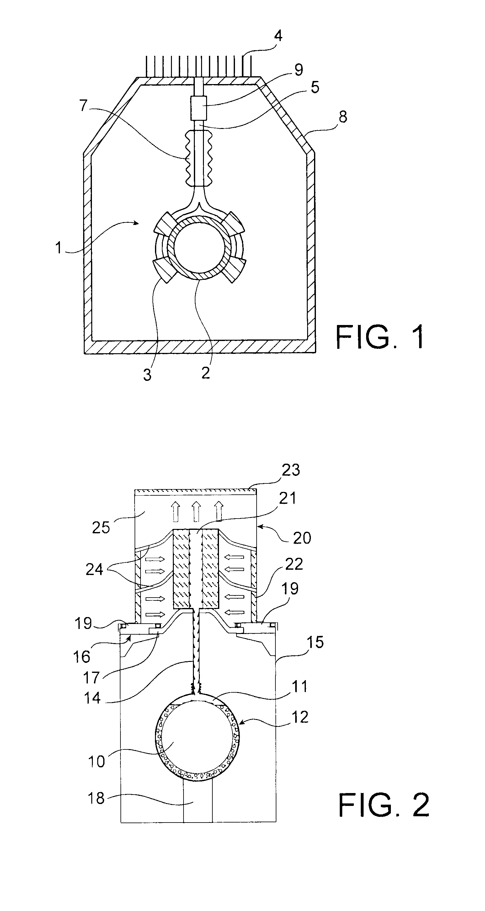
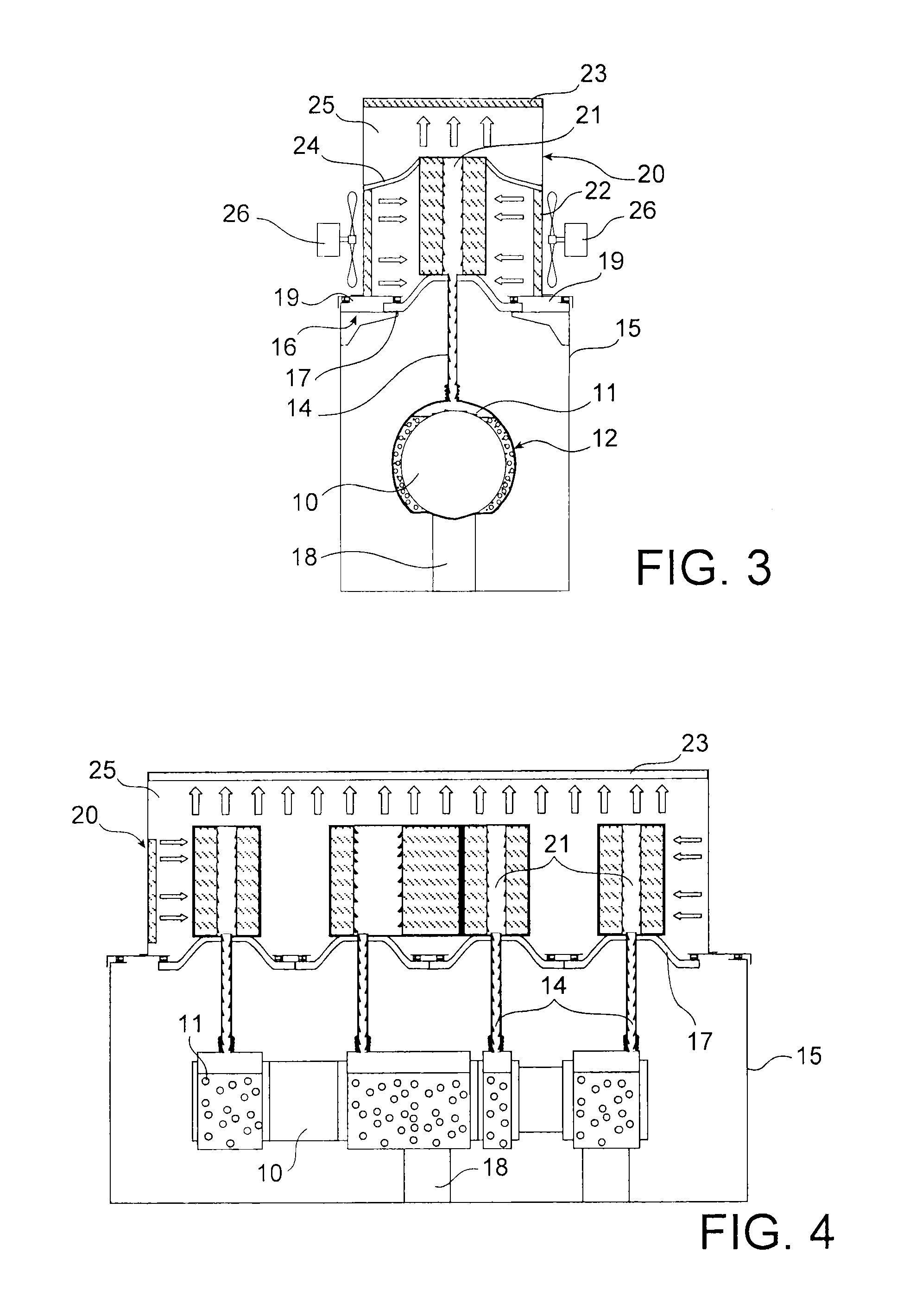
[0019]With reference to FIG. 2, a sheath 15 contains, for example, switchgear, such as a circuit breaker 10, or a busbar section isolator, forming part of a high-voltage electricity transmission installation. Double-walled evaporators 11 containing a phase-change heat-transfer fluid, surround the outside wall of the circuit breaker 10. This circuit breaker 10 and its evaporators 11 form a live assembly 12 and they are supported on the inside of the sheath 15 by an insulating support 18.

[0020]The top portion of the evaporators 11 is connected to at least one pipe 14 that passes through the roof 16 of the sheath 15. Each pipe 14 leads to a condenser 21, which is placed on the roof 16 of the sheath 15. The condenser(s) 21 are themselves placed inside a box 20, which is placed above the sheath 15, and they are subjected to a flow of air, in particular passing through side walls 22 having air passages and through a top space 25 of the box 20, the space being just below the roof 16 of the...


PUM


Abstract

A cooling device including an evaporator operating with a phase-change heat-transfer fluid surrounding electrical switchgear operating at high voltage and connected to one or more condensers placed on a roof of a sheath in which the electrical switchgear is placed. The condensers are supported in this location by insulating elements that include side partitions that are to the side relative to a box, placed above the sheath and/or a central portion of the roof of the sheath. The cooling device consumes very little energy and does not require an electrically insulated cooling system to be designed and can be used, for example, for application to medium-voltage generator circuit breakers.

Description

FIELD OF THE INVENTION[0001]The invention relates in particular to the field of circuit breakers or disconnectors for medium-voltage generators, placed in a protective sheath, and using cooling devices called “heat pipes” that operate with a phase-change heat-transfer fluid.PRIOR ART AND PROBLEM POSED[0002]The constant concern of makers of that type of equipment is to increase the ability of such gear to conduct higher and higher currents, in particular for circuit breakers and disconnectors placed inside busbars at the outlets of power stations for producing or distributing electricity. That applies particularly for alternator circuit breakers.[0003]A method that is generally used consists in making more uniform the temperature of the air that is in contact with the various heating and heated parts of the circuit breaker concerned. The cooling inside such a protective sheath may take place by natural or forced convection of the air enclosed therein and in which the circuit breaker ...

Claims


Application Information

Patent Timeline
IPC IPC(8): F25D31/00
CPCF28D15/0266H01H9/52H01H2009/523H01H2009/526H01L23/427H01L2924/0002H02G5/10H01L2924/00
Inventor FRIGIERE, DENISRODRIGUES, DIDIERWILLIEME, JEAN-MARCJACQUIER, FRANK
Owner ALSTOM TECH LTD
Why Eureka
Try Eureka