Surface modification using abrasive blasting

a surface modification and abrasive blasting technology, applied in the field of engineering components, can solve the problems of high stress, high temperature, high pressure, and/or high temperature conditions, and achieve the effects of preventing the generation and propagation of macro-cracks, improving the consistency of the final component, and maximising the resistance to cracking

Active Publication Date: 2019-02-21
ROLLS ROYCE PLC
View PDF0 Cites 0 Cited by
  • Summary
  • Abstract
  • Description
  • Claims
  • Application Information

AI Technical Summary

Benefits of technology

[0018]The second abrasive blasting operation may act to impart compressive stress into the region. This compressive stress imposes a compressive force on the underlying material, which helps to resist the propagation of cracks in the component. In particular, this helps to prevent the generation and propagation of macro-cracks during a subsequent HIP or heat treatment process.
[0019]The second blasting operation preferably causes no significant material removal from the surface. This improves the consistency of the final component and its compliance with the design requirement.
[0020]The region may be substantially the entire surface of the component. The presence of a compressive stress over the whole surface of the component will maximise the resistance to cracking during subsequent operations.
[0021]The first and second abrasive blasting operations may be performed using the same apparatus and abrasive. The blasting operations are considerably simplified if the same apparatus and abrasive can be used for both, and only the angle of the delivery nozzle changed.

Problems solved by technology

Such porosity or weakness might result in failure of the component under high pressure, high stress and / or high temperature conditions.
A disadvantage of additive layer manufacturing, however, is that it produces components with a rougher surface finish than is achievable with conventional (subtractive) manufacturing methods.
A particular problem is that random semi-sintered particles may be adhered to the component surface, and these can block the media stream from impacting the surface during a subsequent blasting or peening operation.
Such machining operations can be expensive and time-consuming.
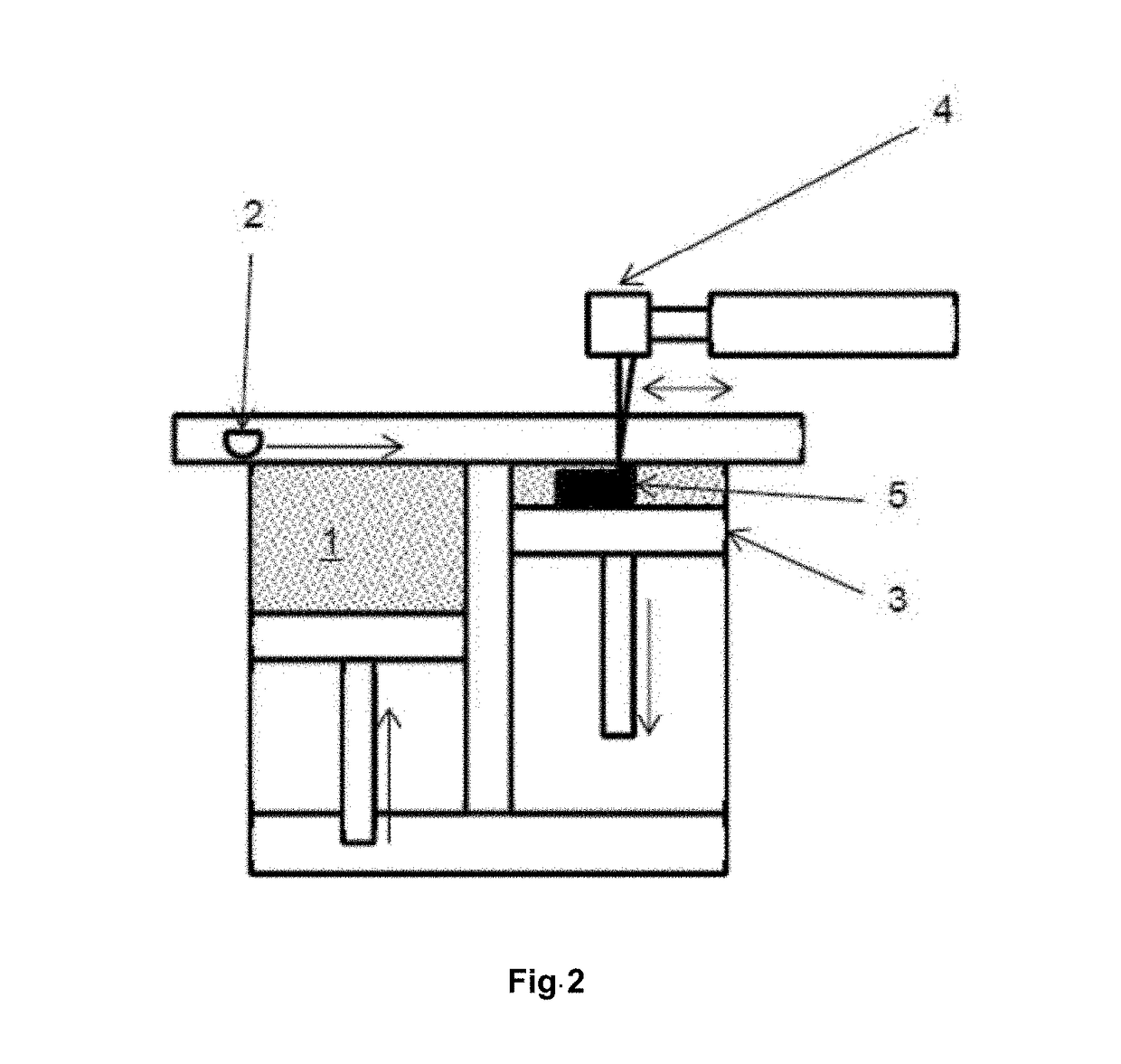
Furthermore, the design freedoms afforded by ALM allow designers to create ever more complex component geometries, and (because of the physical and mechanical limitations of machining tools) creating machining tool paths or alternative surface finishing techniques for such component geometries will become increasingly difficult.

Method used


Image

  • Surface modification using abrasive blasting
  • Surface modification using abrasive blasting
  • Surface modification using abrasive blasting

Examples


Embodiment Construction

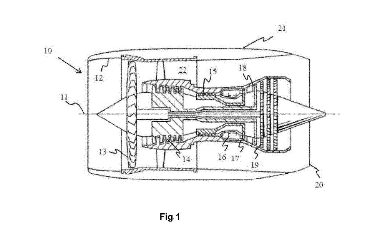
[0029]With reference to FIG. 1, a gas turbine engine is generally indicated at 10, having a principal and rotational axis 11. The engine 10 comprises, in axial flow series, an air intake 12, a propulsive fan 13, an intermediate pressure compressor 14, a high-pressure compressor 15, combustion equipment 16, a high-pressure turbine 17, and intermediate pressure turbine 18, a low-pressure turbine 19 and an exhaust nozzle 20. A nacelle 21 generally surrounds the engine 10 and defines both the intake 12 and the exhaust nozzle 20.

[0030]The gas turbine engine 10 works in the conventional manner so that air entering the intake 12 is accelerated by the fan 13 to produce two air flows: a first air flow into the intermediate pressure compressor 14 and a second air flow which passes through a bypass duct 22 to provide propulsive thrust. The intermediate pressure compressor 14 compresses the air flow directed into it before delivering that air to the high pressure compressor 15 where further com...


PUM

PropertyMeasurementUnit
angle of incidenceaaaaaaaaaa

Abstract

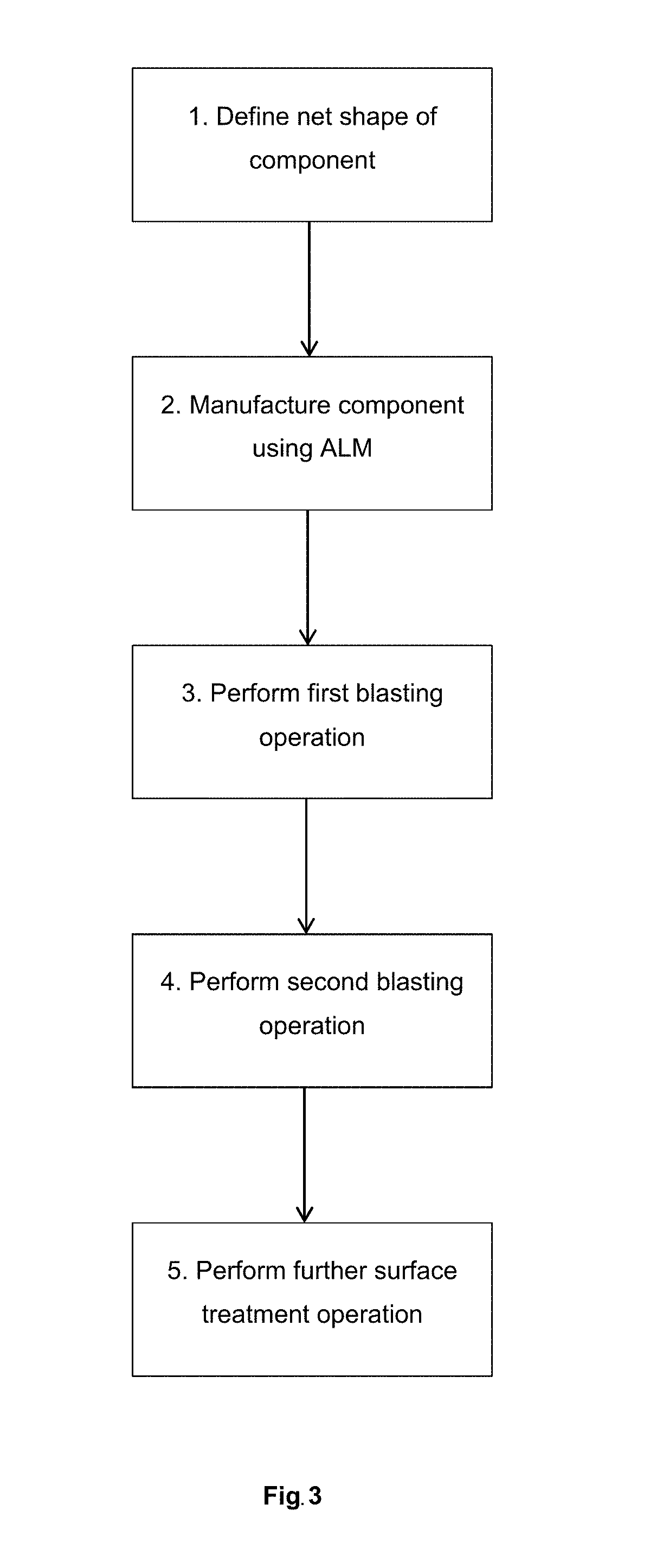
A method for the manufacture of a component comprises the following steps, in sequence using an additive layer manufacturing process to build a three-dimensional net shape of the component; performing a first abrasive blasting operation on a region of a surface of the component; and performing a second abrasive blasting operation on the region. The angle of incidence of the abrasive on the surface in the first abrasive blasting operation is less than the angle of incidence of the abrasive on the surface in the second abrasive blasting operation.

Description

CROSS-REFERENCE TO RELATED APPLICATIONS[0001]This application is based upon and claims the benefit of priority from British Patent Application No. GB 1713300.0, filed on 18th of August 2017, the entire contents of which are herein incorporated by reference.BACKGROUNDTechnical Field[0002]The present disclosure concerns the manufacture of an engineering component, for example a component of a gas turbine engine. More particularly, a method of manufacture involving an additive layer manufacturing (ALM) step and abrasive blasting steps is described.Description of the Related Art[0003]Additive layer manufacturing (ALM) techniques are known for use in forming components with complex geometries and can be used as an alternative to casting. In ALM techniques, a component is built up layer by layer onto a base plate until the 3D component is defined. In some ALM methods, layers are created by selective treatment of layers within a mass of particulate material, the treatment causing cohesion ...

Claims


Application Information

Patent Timeline
Patent Type & Authority Applications(United States)
IPC IPC(8): B24C11/00B22C9/18B24C1/10B29C67/04
CPCB24C11/00B22C9/18B24C1/10B29C67/04B24C1/006B33Y10/00B22F5/009B22F5/04B24C1/08B22F2998/10B22F2003/247Y02P10/25B22F10/28B22F10/66B33Y40/20B22F3/24B22F3/15B33Y40/00
Inventor JOHNSON, CHARLES R HGIBSON, GRANT J.
Owner ROLLS ROYCE PLC
Why Eureka
Try Eureka