Fixing apparatus and image forming apparatus

a technology of fixing apparatus and fixing toner, which is applied in the direction of electrographic process apparatus, ohmic resistance heating, instruments, etc., can solve the problems of recording material curling or wrinkles, and achieve the effects of reducing the quantity of fixers impregnated, preventing curling and wrinkles, and restrainting the fixers

Inactive Publication Date: 2006-05-16
RICOH KK
View PDF8 Cites 49 Cited by
  • Summary
  • Abstract
  • Description
  • Claims
  • Application Information

AI Technical Summary

Benefits of technology

[0008]The present invention is made in view of the foregoing problems, and it is an object of the present invention to provide a fixing apparatus and an image forming apparatus which restrain generation of curls and wrinkles of a recording material even when the wet fixing method is employed as an energy saving measure.
[0012]With the features described above, it is possible to reduce the quantity of the fixer impregnated into the recording material compared with the conventional case where the fixer is imparted to the entire recording material.
[0013]As a method of imparting the fixer as in the present fixing apparatus and the present image forming apparatuses, there is a method of obtaining toner carrying positions on the surface of the toner image carrying body before the toner is transferred to the recording material, or on the surface of the recording material after the toner is transferred based on image information on an image to be formed, for example. By employing this method, it is possible to blow the fixer in an appropriate quantity only to the obtained toner carrying positions, and thus to impart the fixer to the toner without attaching the fixer to surface parts of the recording material which are not carrying the toner. In addition, as another method, for example, there is a method of imparting the fixer on the surface of the toner image carrying body in a state where a toner image is carried while liquid repelling treatment is applied to the surface of the toner image carrying body such that it bears a liquid repelling property in advance. With this method, the fixer imparted to the parts where the toner is not attached is in a state of being repelled from the surface of the toner image carrying body. Thus, it is possible to restrain the fixer from being attached to the parts where the toner is not attached before the surface of the toner image carrying body comes in contact with the recording material after the fixer is imparted. Additionally, even when the more or less fixer is attached to the parts where the toner is not attached, the fixer is attracted by toners around, and consequently, the fixer on those parts disappears. Thus, it is possible to impart the fixer to the toner without attaching the fixer to the surface parts of the recording material which are not carrying the toner.

Problems solved by technology

Consequently, a large quantity of fixer is impregnated into the recording material, and thus, there is such a problem that the recording material tends to curl or wrinkle.

Method used


Image

  • Fixing apparatus and image forming apparatus
  • Fixing apparatus and image forming apparatus
  • Fixing apparatus and image forming apparatus

Examples


embodiment 1

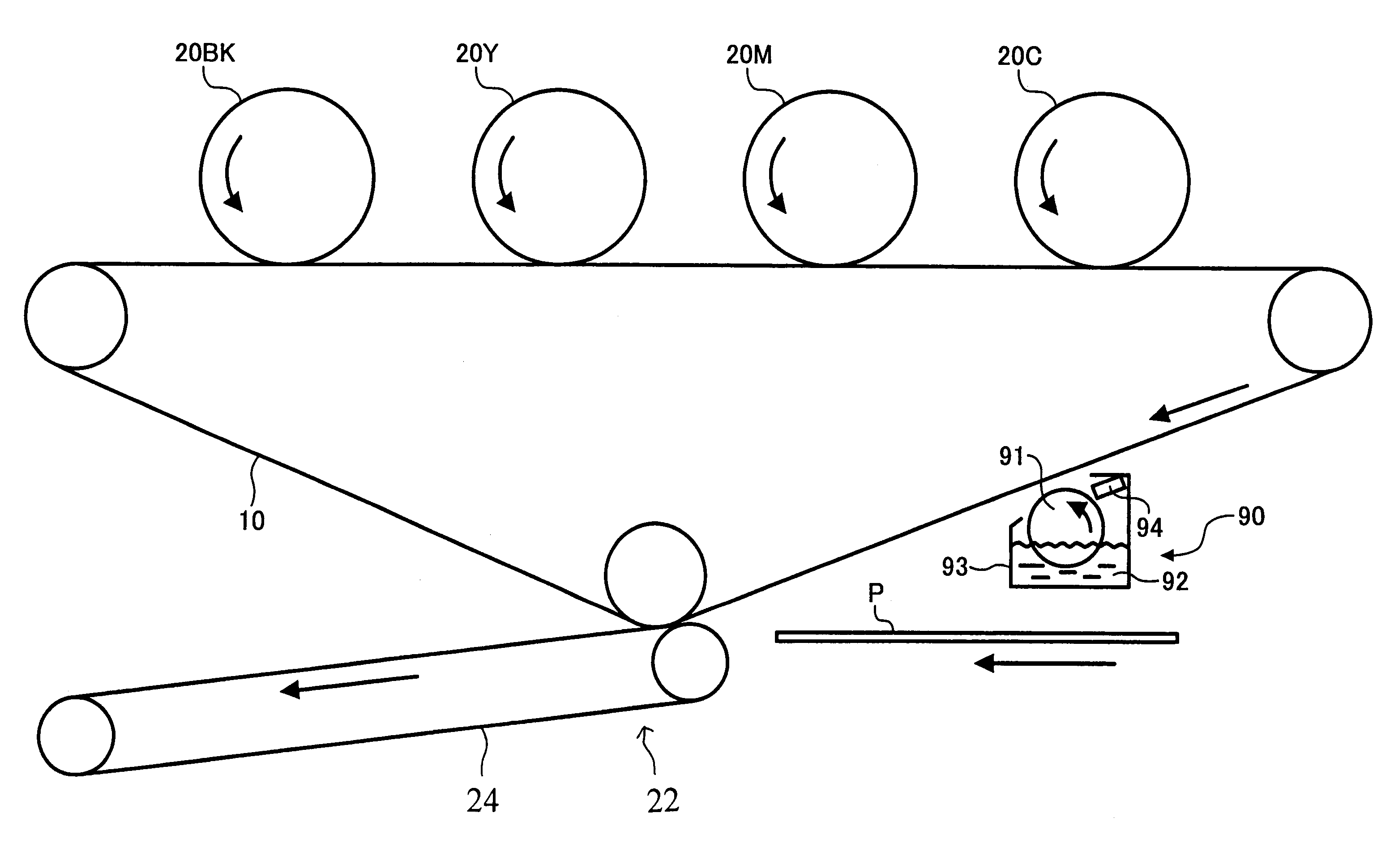
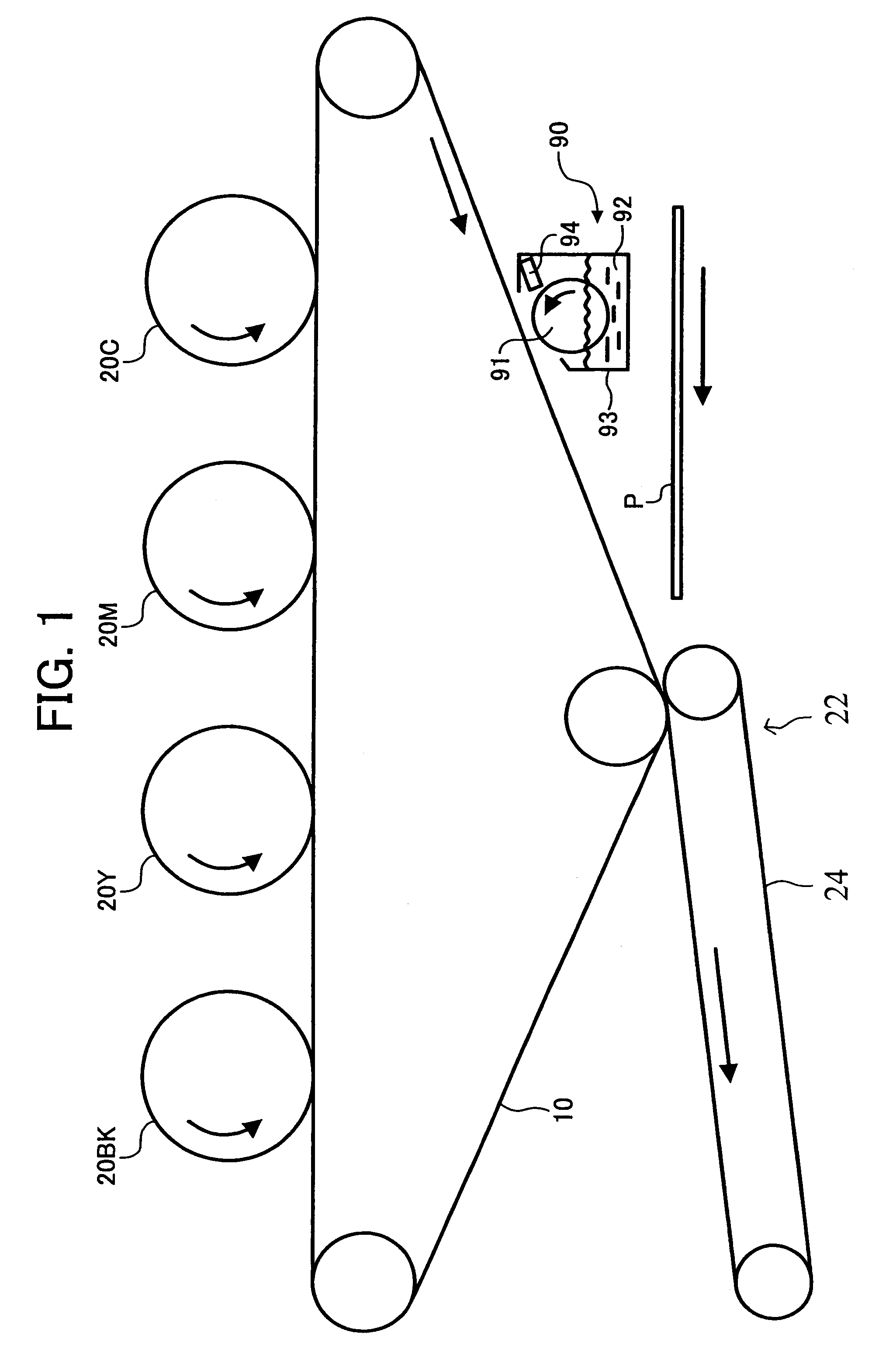
[0030]The following section describes one embodiment (the present embodiment is referred to as “embodiment 1” hereinafter) where the present invention is applied to a color copying machine of electrophotography type (simply referred to as “copying machine” hereinafter) as an image forming apparatus. In addition, the copying machine according to the present embodiment is a so-called tandem-type color image forming apparatus provided with an intermediate transfer belt which is a toner image carrying body.

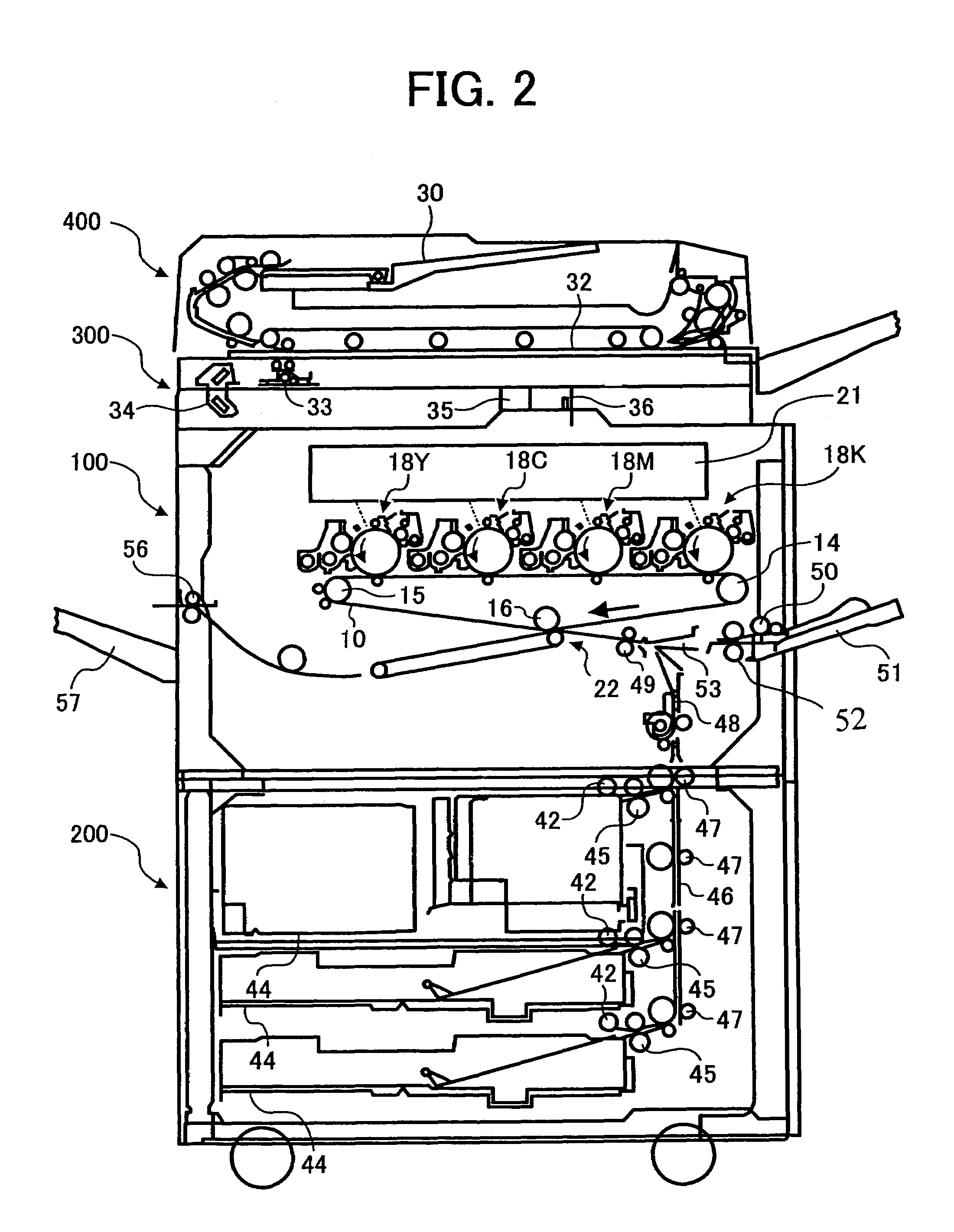
[0031]FIG. 2 is a schematic constitution diagram of the entire copying machine according to the present embodiment. This copying machine is constituted by a copying machine main unit 100, a paper feeding table 200 for placing the copying machine main unit, a scanner 300 installed on the copying machine main unit, and an automatic document feeder (ADF) 400 installed on the top of the scanner.

[0032]FIG. 3 is an enlarged view showing the constitution of a part of the copying machine main...

example 1

CONSTITUTION EXAMPLE 1

[0071]The following section describes another constitution example (referred to as “constitution example 1” hereinafter) of the fixing apparatus according to the embodiment 1.

[0072]FIG. 6 is a schematic constitution diagram showing a fixing apparatus 190 of the present constitution example 1. This fixing apparatus 190 is common to the fixing apparatus 90 of the embodiment 1 in terms that a supplying roller 191 supplies the surface of the intermediate transfer belt 10 with the fixer 92. However, in the fixing apparatus 190 of the present constitution example 1, how to measure the quantity of the fixer attached on the surface of the supplying roller 191 is different from that in the embodiment 1. Namely, while, in the embodiment 1, the metering blade 94 measures the fixer quantity on the supplying roller 91 an applying roller 195 measures the quantity in the present constitution example 1.

[0073]FIG. 7 is a front view showing the applying roller 195. As shown in t...

example 2

CONSTITUTION EXAMPLE 2

[0076]The following section describes another constitution example (referred to as “constitution example 2” hereinafter) of the fixing apparatus according to the embodiment 1.

[0077]FIG. 8 is a schematic constitution diagram showing a fixing apparatus 290 of the constitution example 2. This fixing apparatus 290 is different from the embodiment 1 and the constitution example 1 in how to supply the fixer 92 on the surface of the intermediate transfer belt 10. Namely, in the constitution example 2, the fixer 92 is foamed, and then, is supplied on the surface of the intermediate transfer belt 10. Different methods may be used to foam the fixer 92. For example, there is such a method that the fixer 92 containing the surface active agent is foamed by supplying compressed air from a compressor. As a method for generating finer foam, there is such a method that the fixer 92 is blown through a porous filter having holes with a minute diameter such as ceramics or a materi...


PUM


Abstract

Since a fluorine treatment or the like is applied on a surface of an intermediate transfer belt (10), and thus, the surface bears water repelling property, when fixer (92) is supplied from a fixing apparatus (90) to surface parts of the intermediate transfer belt which are carrying a toner image, the fixer is present only on the toner parts. Namely, the fixer is not attached to surface parts which are not carrying the toner. Consequently, when the surface parts are pressed on transfer paper (P) for transferring and fixing, the fixer attached to the transfer paper is present only on the parts of the toner T. Thus, compared with a conventional case where fixer is imparted to entire transfer paper, a reduced quantity of the fixer is impregnated into the transfer paper, and thus, generation of curls and wrinkles of the transfer paper is restrained.

Description

CROSS-REFERENCE TO RELATED APPLICATIONS[0001]This application is a continuation application of, and claims priority to, Ser. No. 10 / 664,868 filed on Sep. 22, 2003 now U.S. Pat. No. 6,947,700 and claims priority to Japanese Patent Application No. 2002-274602 filed on Sep. 20, 2002, the entire contents of each of which are hereby incorporated herein by reference.BACKGROUND OF THE INVENTION[0002]1. Field of the Invention[0003]The present invention relates to a fixing apparatus for imparting a fixer solving or swelling a toner to the toner, and then and for fixing the toner on a recording material, and to an image forming apparatus including the same fixing apparatus such as a copying machine, a facsimile, and a printer.[0004]2. Description of the Prior Art[0005]Conventionally, an image forming apparatus employing heat fixing method which heats and melts a toner on a recording material, and then, presses the toner to fix it on the recording material is known. In this type of the image f...

Claims


Application Information

Patent Timeline
Patent Type & Authority Patents(United States)
IPC IPC(8): G03G15/20G03G15/16
CPCG03G15/2096
Inventor KUROTORI, TSUNEOOHDAKE, EISHUTAKEUCHI, NORIYASU
Owner RICOH KK
Why Eureka
Try Eureka