Film-Forming Apparatus And Film-Forming Method

a film-forming apparatus and film-forming technology, applied in lighting and heating apparatus, discharge tube luminescnet screens, natural mineral layered products, etc., can solve the problems of element not working, dark spots or variation in element lifetime, etc., to increase the film-forming rate, prevent unnecessary adhesion, and uniform film formation

Inactive Publication Date: 2008-10-02
OHMI +1
View PDF24 Cites 51 Cited by
  • Summary
  • Abstract
  • Description
  • Claims
  • Application Information

AI Technical Summary

Benefits of technology

[0032]According to this invention, since an evaporated film-forming material reaches the surface of a substrate by the flow of a transport gas, the film-forming conditions can be controlled by the flow of the gas and hence a uniform thin film can be deposited on the large-area substrate. That is, by directing the evaporated raw material toward the substrate, it is possible to increase the film-forming rate and achieve uniform film formation. For example, approximately one to two minutes are enough for forming a three-color organic EL layer on a glass substrate having a size of 400 mm×500 mm and hence the film-forming time can be shorted to 1 / 10 or less as compared with conventional. By directing the evaporated raw material toward the substrate, by raising the temperature of a portion other than the substrate to an evaporation temperature or more to prevent unnecessary adhesion of the evaporated raw material, or by using a heavy gas such as xenon for transport so as to fix the flow of the raw material in a constant direction, the expensive raw material can be selectively adhered only on the substrate, thereby enabling highly economical film formation with a waste of the raw material eliminated. Further, since use is comprised of the method that transfers the evaporated film-forming material on the flow of the transport gas, it is possible to stop ejection of the raw material by stopping the flow of the gas during non-film formation and hence it is possible to prevent generation of waste of the raw material.
[0033]The film-forming apparatus of this invention thoroughly eliminates generation of the organic compound contamination substance / material decomposition dissociation substance that adversely affects the properties of the film-forming material, and thus can deposit a high-quality thin film. By using the film-forming apparatus of this invention for forming an organic EL element, it is possible to obtain a high-quality organic EL display device with high brightness and long lifetime.

Problems solved by technology

However, although the film thickness of an organic EL element formed in the apparatus of such a structure is uniform, dark spots or variation in element lifetime occurs.
Further, according to the injector described in Patent Document 1, there arises a problem that since there is no disclosure about the material and temperature of the injector, the organic EL material is deposited inside the injector and decomposed inside the injector depending on the conditions, thereby causing deposition of the decomposition product on the substrate, so that the organic EL element does not function.

Method used


Image

  • Film-Forming Apparatus And Film-Forming Method
  • Film-Forming Apparatus And Film-Forming Method
  • Film-Forming Apparatus And Film-Forming Method

Examples


embodiment 1

[0124]Hereinbelow, Embodiment 1 of this invention will be described with reference to the drawings.

[0125]The materials each adapted to evaporate the organic EL material into the gas phase without decomposition / dissociation have been made clear. Description will be next given of an apparatus adapted to form a film of an expensive organic EL material on a glass substrate, plastic substrate, or metal substrate quite efficiently and at a high rate without decomposing / dissociating organic EL molecules.

[0126]Referring to FIG. 26, description will be given of the mechanism for evaporating an organic EL material with respect to a substrate 32 located in a process chamber (container to be depressurized) 31, thereby carrying out film formation on the substrate 32.

[0127]In FIG. 26, there are included valves 11 to 20, the process chamber 31, the substrate 32, a stage 33, a gas ejection plate 34, an organic compound molecule ejection apparatus 35, an evaporation dish 36, ring-shaped gas ejection...

embodiment 2

[0146]When organic compound molecules having a certain weight, i.e. a molecular weight of several hundreds to approximately 1000, are contained in a heavy base gas such as Xe or Kr and irradiated onto a substrate, the gas flow accurately reaches the substrate surface, which is thus more preferable. The organic compound molecules, which are solidified near room temperature, are adsorbed on the substrate surface and only the Xe gas or Kr gas is discharged to the outside by the exhaust pumps. Xe and Kr are highly expensive gases as compared with Ar and N2 that are normally used industrially. It is desirable that a Xe or Kr recovery circulation system be provided subsequently to the roughing vacuum pump.

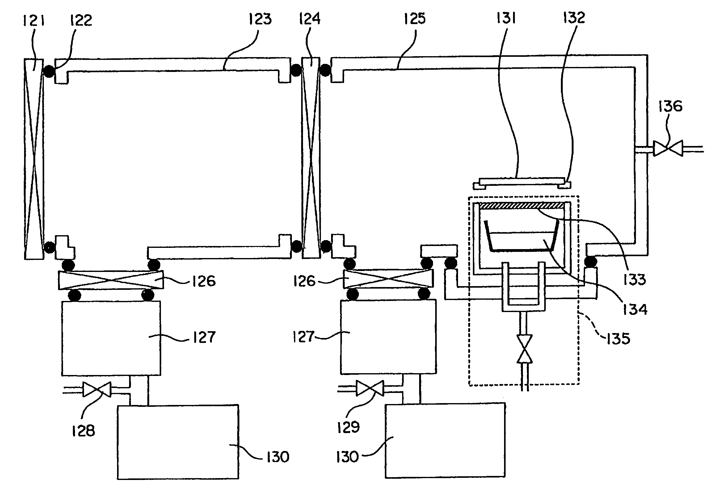
[0147]FIG. 34 shows a system for recovering / circulating an Xe gas or a Kr gas. In FIG. 34, a turbo-molecular pump 77 coupled to a chamber 75 through a valve is coupled to a roughing vacuum pump 78 and the turbo-molecular pump 77 and the roughing vacuum pump 78 receive Ar or N2 and exhaus...

embodiment 3

[0152]The lifetime and luminous properties of an organic EL element can be improved by removing organic compound contamination of an organic EL thin film. On the other hand, when transferring a glass substrate to a film-forming apparatus after cleaning, if use is comprised of a transfer apparatus that does not cause organic contamination on the substrate surface, the lifetime and luminous properties can be further improved. For such transfer of the glass substrate, it is most desirable to transfer the substrate, facing upward or downward, by gas levitation transfer with a clean dry air using porous ceramics as shown in FIG. 39 as an example. As shown in Embodiment 1 as the examples, when the substrate surface (the surface to be deposited with a film-forming material) faces upward in the film-forming apparatus, it is preferable that the substrate surface face upward during gas levitation transfer, when the substrate surface faces downward in the film-forming apparatus, it is preferab...


PUM

PropertyMeasurementUnit
temperatureaaaaaaaaaa
pressureaaaaaaaaaa

Abstract

For increasing the film-forming rate and enabling uniform film formation and waste elimination of raw material, a film-forming method and a film-forming apparatus can reach an evaporated film-forming material to a surface of a substrate by the flow of a transport gas so as to control the film-forming conditions by the flow of the gas. Thereby a uniform thin film can be deposited on the large-area substrate. That is, by directing the evaporated raw material toward the substrate, it is possible to increase the film-forming rate and achieve uniform film formation.

Description

TECHNICAL FIELD[0001]This invention relates to a film-forming apparatus and a film-forming method for forming a film layer of a predetermined material and, in particular, relates to a film-forming apparatus and a film-forming method for forming a film layer of a predetermined material by evaporating a raw material of the predetermined material.BACKGROUND ART[0002]Methods for forming a film layer of a predetermined material by evaporating a raw material of the predetermined material are widely used in the manufacture of such electronic devices as semiconductor devices, flat panel display devices and others. As one example of such electronic devices, description will be given hereinbelow of an organic EL display device. The organic EL display device with sufficiently high brightness and a lifetime of several tens of thousands of hours or more uses an organic EL element that is a self-luminous element and thus can be formed thin with less peripheral components such as a backlight. Ther...

Claims


Application Information

Patent Timeline
Patent Type & Authority Applications(United States)
IPC IPC(8): B05D5/12C23C16/54H01J1/63C23C14/12C23C14/24C23C14/54C23C14/56C23C16/448F28F13/08F28F27/02H05B33/10H05B33/28
CPCC23C14/12C23C14/228C23C14/243F28F13/08C23C14/564F28D2021/0077F28F9/026C23C14/541
Inventor OHMI, TADAHIROMATSUOKA, TAKAAKI
Owner OHMI
Why Eureka
Try Eureka