Punch device with interchangeable punch and variable punch pattern

a technology of punching device and punching pattern, which is applied in the field of punching device, can solve the problem and achieve the effect of avoiding the risk of punch damag

Active Publication Date: 2008-11-20
GROZ BECKERT KG
View PDF7 Cites 6 Cited by
  • Summary
  • Abstract
  • Description
  • Claims
  • Application Information

AI Technical Summary

Benefits of technology

[0010]By shifting the selection plate, individual punch holding bars may be activated or deactivated, i.e., they are involved or not involved in the punch stroke. In addition, the selection plate as a whole may be taken off in order to permit access to the holding bars and the punches supported therein. In this manner, the punches can be replaced or maintained in a simple manner. This requires neither special dexterity nor training. When removing

Problems solved by technology

In addition, the risk of dam

Method used


Image

  • Punch device with interchangeable punch and variable punch pattern
  • Punch device with interchangeable punch and variable punch pattern
  • Punch device with interchangeable punch and variable punch pattern

Examples


Embodiment Construction

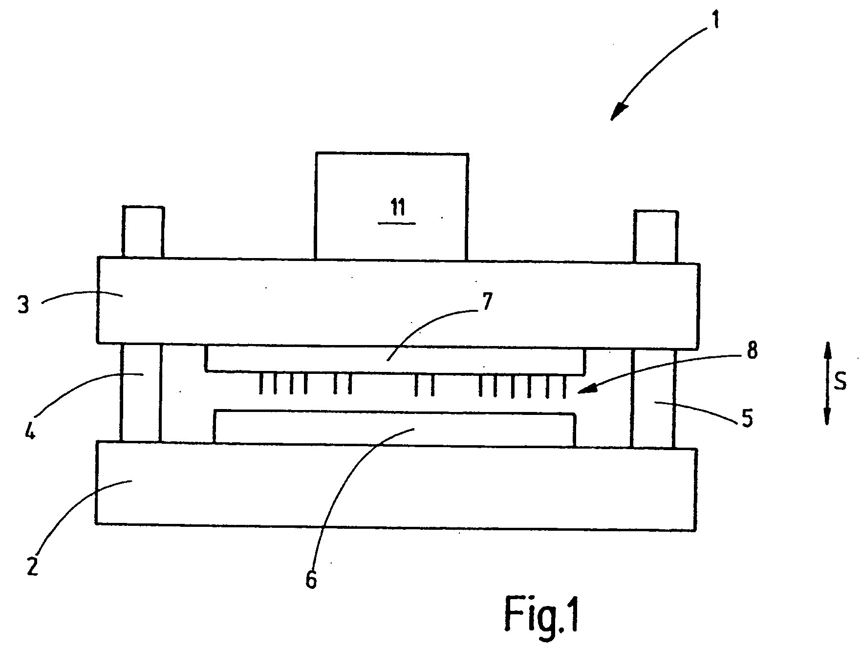
[0016]FIG. 1 shows a punch device which is used to produce a pre-specified hole pattern in a planar object such as, for example, a green sheet. Green sheets are understood to mean unfired ceramic substrates, as are used, for example, in the production of ceramic supports that have electronic circuits.

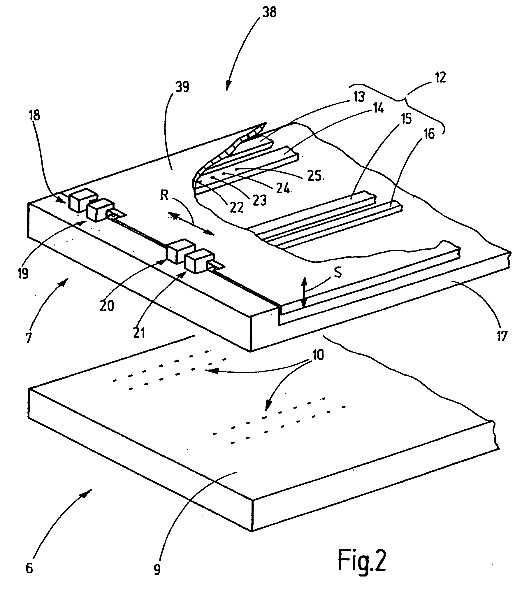
[0017]The punch device 1 has an outer frame with a lower frame part 2, an upper frame part 3 and guides 4, 5. The lower frame part 2 supports a lower tool part 6. The upper frame part 3 supports an upper tool part 7. The upper tool part 7 is provided with a number of punches 8 that are aligned parallel to each other and face in the direction of the lower tool part 6. The lower tool part 6 supports a die 9, as is shown by FIG. 2. This die is provided with a number of punch openings 10 into which the punches 8 may immerse, once they have passed through the workpiece. The punch openings may contain (not illustrated) cutting sockets.

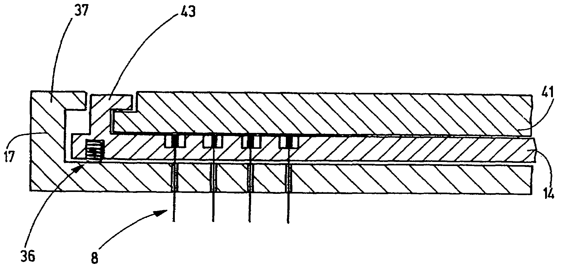
[0018]The upper frame part 3 and / or the upper tool part 7 ...


PUM

PropertyMeasurementUnit
Pressureaaaaaaaaaa

Abstract

A selection plate (39) is provided on a punch device (1) for activating or deactivating individual punch holding bars (13, 14). The plate has a coupling device (40) associated with a positive-locking coupling between a punch holding bar (13, 14) and the selection plate (39). Associated with the positive-locking coupling is an edge of the selection plate (39), that is provided with a recess (42), an extension (43) of the punch holding bar (13, 14) that extends around said edge, and/or a rib (41), which is located on the underside of the selection plate (39) and is associated with the punch holding bar (13, 14). As a result, it is possible to selectively establish or eliminate a positive-locking connection between the punch holding bar (13, 14) and the selection plate (39). Via the rib (41), the punch stroke of the selection plate (39) is merely transmitted to the punch holding bar (13 or 14), which is in positive-locking engagement with the lateral edge or the projections of the selection plate (39). The elongated rib (41) covers the heads (26, 27, 28, 29) of the punches (8) and transmits the stroke in a planar manner to the punch holding bar (13 or 14).

Description

CROSS-REFERENCE TO RELATED APPLICATION[0001]This application claims the priority of European Patent Application No. 07 009 594.8, filed May 14, 2007, the subject matter of which, in its entirety, is incorporated herein by reference.BACKGROUND OF THE INVENTION[0002]The invention relates, in general, to a punch device and, in particular, to a punch device intended for punching holes into “green sheets” (unfired ceramic substrates).[0003]When punching green sheets, a large number of holes are to be made in a ceramic substrate. To achieve this, an appropriate number of punches are used. The punches are aligned parallel to each other and are simultaneously pushed through the green sheet. In so doing, the green sheet is situated on a die having corresponding punch openings.[0004]Such a punch device has been known, for example, from DE 198 55 578 A1 and U.S. Pat. No. 6,481,323 B1. The punch device comprises a lower and an upper tool part, whereby the lower tool part is a die. The upper too...

Claims


Application Information

Patent Timeline
IPC IPC(8): B26F1/14B26F1/40B26D5/00
CPCB26D5/08B26D7/2614B26F1/14B26F1/24H05K1/0306H05K3/005Y10T83/8727Y10T83/943Y10T83/9432
Inventor HORN, KUNOHEINEMANN, ERNST
Owner GROZ BECKERT KG
Why Eureka
Try Eureka